Interestingly, he also demonstrates the effect of changing rotor field.
This is a good starting point for the Prius position sensors.
Simple initial circuit
As with the field control it's a good idea to start simple.
This means using reed switches and magnets for sensing position, and probably using a diode matrix as the logic to drive the outputs.
So going back to the simple relay-based controller and swapping out the reed relays with reed switches.
Since the relays are not a one-to-one with reed switches we need to introduce a diode matrix.
For the sequence table see the Software Lab, where there are some interactive animations to play with.
Just doing the simpler 6-step sequence to get going.
This will be limited by the slow electro-mechanical components, but it should start and run when power is applied.
It allows us to build and test the mechanical parts, before moving to the solid state version with hall sensors and MOSFETS.
There's something reassuring seeing and checking the mechanical parts working before trying the solid state versions.
Also it helps gain confidence in the solution before things get obscure.
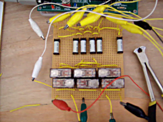
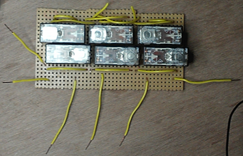
So we revived the relay board used in the first motor prototype:
This got a bit butchered making the relay-based Prius controller but we have the output relay part:
So the board is prepared for use with the usual croc-clip terminals:
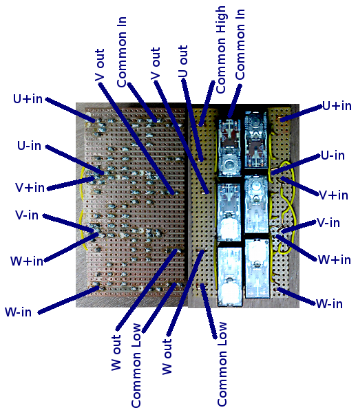
The diodes used in the matrix board were just some stock ones which are well above the required rating.
The DSR15V600 used are actually a 600V/15A diode.
The relay coil is 12v and draws about 50mA so we have enough margin!
The diode matrix board was constructed from perforated board and wire:
If you don't like the stereoscopic 3D just switch it off.
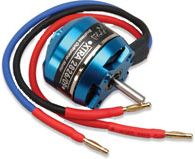
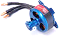
We are re-using the radio controlled helicopter brushless motor:
The controller worked surprisingly well considering it is a simple electro-mechanical design:
If you don't like the stereoscopic 3D just switch it off.
Upgrading the design to solid state
So we need to upgrade the design to the solid state version.
Swap out the relays for MOSFETs since this is a straight forward modification.
Just need to add the split rail supply, which we were already using since the motor circuit used a separate supply from the sensors anyway.
Using the same IRL2203Ns and 220R switch off resistors it's pretty much a straight swap for the relays:
Straight away you see a speed increase, but it was huge.
Those reed switches are surprisingly fast and the poor magnets held to the card with tape were spun off!
If you don't like the stereoscopic 3D just switch it off.
Next upgrade the reed switches to hall sensors.
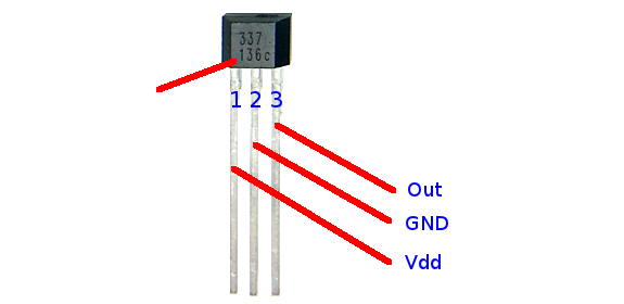
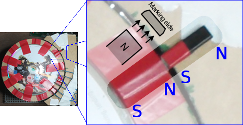
So the AH337-PL-B is used.
The datasheet doesn't make the pinout clear, it refers to the "top" of the device, but the diagram seems to show the back.
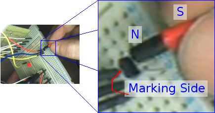
Also usually the marking is added to the largest surface, but on these devices it's the opposite one.
It seems the guys who organised the printing of the devices messed up and printed the wrong side, so the documentation was botched.
This is extracted from the datasheet, fixed and verified by in circuit testing:
The circuit above is OK,
but it would tie in better with the Field Control stuff if the PNP transistors driver the gates directly and not through the diode matrix.
So the circuit was adapted to put the diode matrix driving the PNP bases:
A new motor-sensor set up was constructed from a different motor:
This was to address the flimsy construction of the first one,
also to mount all the PCBs on a piece of wood along with the motor and sensors.
Before the solid state version was tested, as an intermediate step, the relays were used to driver the motor from the hall sensors:
One obvious thing you notice about this controller is the lack of a micro-controller of any form.
This was deliberate so we could prove a controller with a very low component count.
Adding in a MCU obviously increases the component count to around 1 million (if you count the MCU internal components themselves).
This circuit (without an MCU) can power a motor simply by adjusting the power available in the low-side supply.
Indeed that is exactly how the motor is currently controlled.
In a car, it may be better to use an MCU since the motor control is a key part of the performance and feel of the car.
A design using monostables in the sequence to control the motor torque and speed would be perfectly acceptable and doable.
It may ultimately be tested also and employed as a backup system in the event of MCU failure.
However, an MCU provides much more accurate control and also allows for things like non-linear power curves to make the car feel much more like current cars.
This may be key to the success of the final design as people are much more used to piston-engined power which has non-linear power and torque curves.
Positive rail adjustment
Since the controller is going to use an Arduino, which operates on 5vDC and sources/sinks 5v logic we need the high supply to be +5v and not +12v.
There is no need for 12v to power the relay coils the high side supply can be switched to 5v and it should not change the operation.
Of course, the low side supply is only relevant to the motor.
The hall devices require 4.2v - 30vDC so 5v should not be a problem.
The only other issue is the gate charge voltage which was calculated for 12v,
but this simply means the gates may take twice as long to charge (around 2-3uS).
The discharge will happen quicker as a result of the lower voltage so this simply means we offset the on period by around 1uS which will not really be perceivable.
So this was done while the motor was running and, as expected, there was no perceivable change in the operation.
So we have a new circuit which puts the Arduino in place of the diode matrix, including the mark and space pots:
The supply is still 12vDC as this is what the Arduino board requires and it supplies the 5v for the port inputs.
For the Arduino programming please see the Software Lab.
Minimum complexity
Next step with this might be to add ratiometric hall sensors it would be a simpler mechanical design.
It would, however, need accurate, high speed ADCs which probably means the Arduino ones are not going to be enough.
This alone would mean that external components would be needed so the electronic design would be more complex as well as the software.
It seems we have reached the minimum complexity for the position sensing electronics, so this part of the project is complete.
Full project in motion:
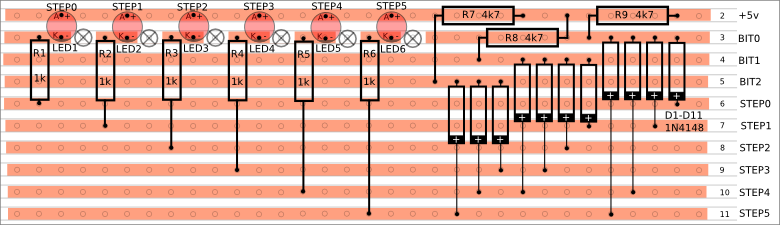
Now the full circuit has been extensively tested it is being committed to PCB:
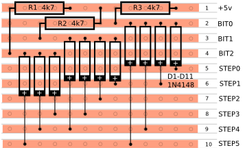
Since the number of inputs on the Arduino (and MCU really) is limited,
a diode matrix is used to convert the 6 position sensors to a 3-bit binary index.
This is commonly converted using Gray Code.
The reason a straight binary conversion is not used is it can lead to position conversion errors.
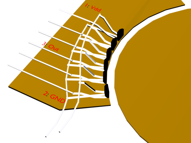
Raw sensing is a hack to get MG1 to provide sensor information from the rotor magnets used for traction.
The issue is they are too long for sensing purposes so they cover 2 or 3 sensors which messes up the Gray code converter.
To get this to work the raw sensor information is provided to the MCU bypassing the Gray code converter and the software uses it directly.
This means there are no lines free for ethernet comms so there cannot be a fast link to the Raspberry Pi for nice whizzy graphics :)
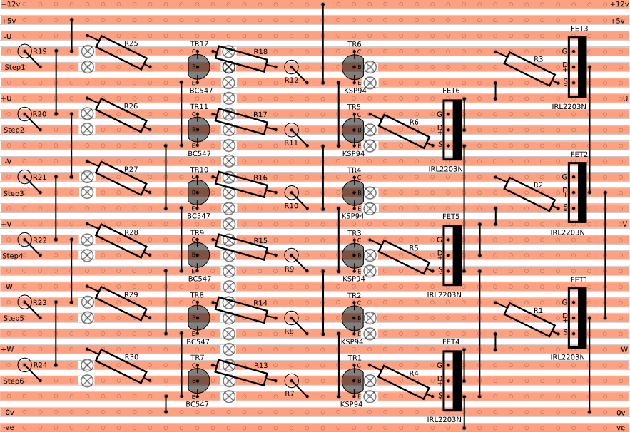
In this circuit the transistors are used as AND gates where the base and collector are the inputs and the emitter is the output.
Here there needs to be 3 consecutive sensors on for an output to the Gray code circuit.
PIC Version
This is implementing the mark-space timing using an external 556:
 Drilling mask: