High Voltage Charging
BIG FAT WARNING!
These MAINS and HIGH VOLTAGE experiments can kill you!
These MAINS and HIGH VOLTAGE experiments can kill you!
In order to charge this car's battery it will need a high voltage charger.
Or we attempt to charge the 60 x 12v batteries in parallel.
Fortunately this is quite easy and cheap.
Mains power in the UK is 240vAC.
The packs in the Mass-EV are going to be arranged as 3 x 20 batteries.
Each battery is, of course 12vDC thus giving a pack voltage of 240vDC.
Total voltage of 3 x 240 = 720vDC.
This is, of course, the design to make charging from domestic mains easy and cheap.
When charging, the packs will be charged in parallel so we only need to charge a 240vDC pack.
If this gets sold in America I guess it will have to have 6 x 120vDC.
Rectified mains peaks at 240vAC x 1.414 (squareroot of 2) = 339.4vDC.
Or about 340vDC so has plenty of voltage difference to charge the battery.
We obviously need to control this as we don't what to overcharge the battery.
We can do this by controlling the AC input to the rectifier using a simple circuit
which normally is incorporated into a dimmer unit for domestic lights.

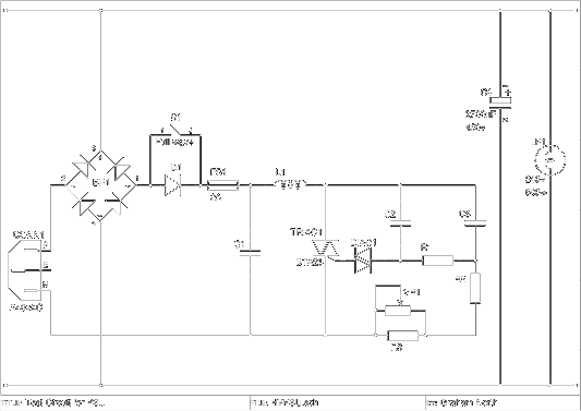
This circuit was originally published on Electronics Project Design
I recreated the schematic from that image.
I recreated the schematic from that image.
It works by removing part of the rising edge (or falling edge on negative sweep) of the phase using a triac circuit.
You can reduce the output by up to 50% linearly.
There's some information about it on epanorama.net.
You can further reduce the output by half wave rectification also, giving a pretty good range.
Certainly enough for the charging of the battery.
The dimmers are sold in DIY stores for under £10 so I purchased one and modified it with a more powerful heatsunk TRIAC.

Pin Layout of the BTA26
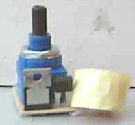
The dimmer is from maplin:
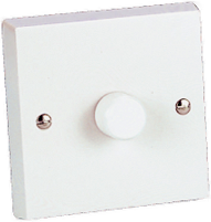
Image of the dimmer from Maplin's website.
Some shots of the board removed from the dimmer:
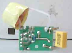
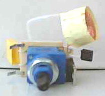
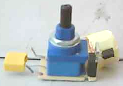
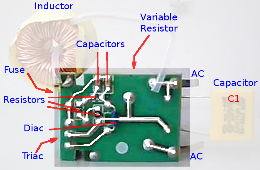
Better shot of the PCB with some detail.
Once the existing triac was removed it can be identified and the pinout discovered from the datasheet:
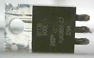
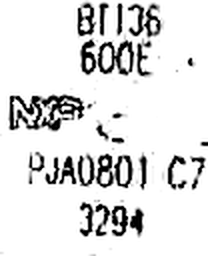
Pin Layout of the BT136
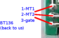
So now we can connect the new high power triac in place, via extending wires.
Of course, we could use this as a 6kW dimmer!
The heatsink and triac were £10 plus a bridge (£2) and a second bridge and switch to use one diode for half wave rectification.
Add a case and wiring and the whole charger comes in around £30.
This gives 13A at around 85v to 340v DC.
The 3 packs are 240vDC 40Ah each giving 240vDC 120Ah in total.
At a 13A charge this would be 120Ah / 13A = 9.23 hours.
So it's quite capable of charging 3 x 240vDC 40Ah lead acid pack to full charge overnight.
In reality you would charge at 12A for a 10 hour charge.
The unit components are actually rated up to 25A so this could charge much faster:
At a 25A charge this would be 120Ah / 25A = 4.8 hours.
For this you would need to have a special supply from your meter.
Also the batteries would probably need cooling, venting and monitoring since they are charging at a much higher rate.
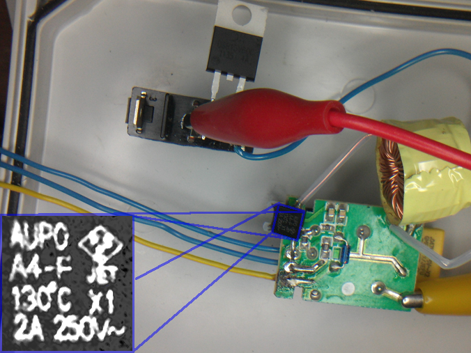
Testing
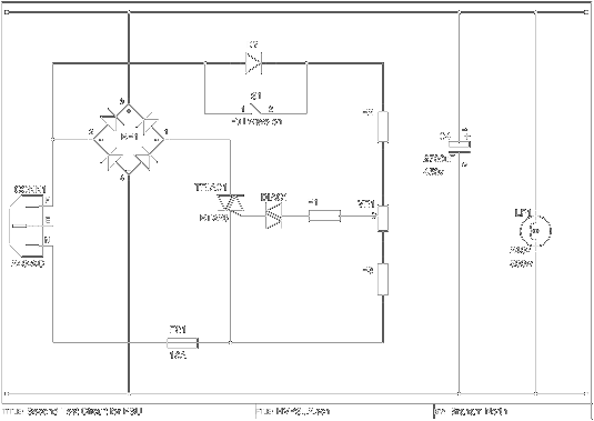
So work finally began on this as it is now needed to charge the batteries we are going to use in the first prototype.The circuit actually tested was:
This seemed to work in that we could vary the average voltage of a 500w/250vAC lamp.
This was, of course, being fed with a variable DC voltage and not AC.
The capacitor was added to measure the RMS DC voltage and verify the meter's reading.
In the final ciruit it will not be needed as the battery does not need a smoothed supply.
There was an issue with the choke once the capacitor was added.
It was being heated.
I guess this was because the current was spiking as it recharged the capacitor during each phase.
This would cause high reactance in the choke.
As a test the choke was shorted to see if it worked OK, but this blew the 2A fuse quite dramatically.
This would again be because at switch on a high current would pass for the initial charge of the capacitor.
Apart from the choke there was nothing even remotely warming up.
Not even the TRIAC, although it was only loaded to 4A.
It the real charger it will run around 12A which it still well below the 25A rating.
Even though the ciruit did OK, it would benefit from being designed more for this purpose.
Voltage
Since the lamp was loading the output the RMS voltage was read from the meter, but we really need to see the peak voltage.This should be around 340v.
As the battery charges the load should decrease and the average voltage should rise.
This would be working as a rugged uniform current charger.
There is an issue with seeing the waveform.
My scope is 100v maximum.
I will need a potential divider to see the waveform using this scope.
I'm guessing 100k high and 10k + 1k low should give me around 10% scale so the voltage should not rise above 34v on the scope.
So we tested this ciruit and experimented with different values for R1, R2 and R3.
Using a value of 0 for R2 and 6.8k (high power resistors !) we didn't really get better than 75% phase.
The low power control was pretty good, but not being able to reach the full power was a limitation.
Inspecting the standard dimmer circuit I understand why it was in this configuration.
The gate was switched from the supply across the TRIAC itself so that when the TRIAC conducted it removed the gate input.
This means you can achieve near 100% phase if the gate is connected to MT2 directly.
Undertanding Triacs
TRIAC or Triode for Alternating Current is the equivalent of a thyristor for AC.
Since AC effectively switches off every half cycle this means it does not lock on in the same way as a thyristor.
The TRIAC does lock on, but only until the end of the current half cycle.
It's like having PWM but without the complex timing circuit.
Since it's AC you get the timing bit for free.
So we tried out the redesigned circuit and it was indeed more stable, but the current in the gate circuit was a bit too high.
The gate circuit in the TRIAC as little resistance so will blow the TRIAC if connected directly to a supply.
This meant it would be better to connect it to the MT2 so the gate supply would be removed when the TRIAC conducted.
A revised circuit was tested:

Charging Times
NiMH cell has an internal resistance of 0.17 ohmsWe have 38 of 6 cells so 228 cells.
Total resistance is:
R = 228 * 0.17
R = 38.76 ohms
NiMH cell has a voltage of 1.2v per cell, so
Vbatt = 1.2 * 228
Vbatt = 273.6v
Terminal voltage was actually 285v so the cell voltage is actually 1.25v.
I believe this the no-load voltage.
The battery potential is raised from 285 to about 298 so
Vcharge = 298 - 285
Vcharge = 13v

I = V / R
I = 13 / 38.76
I = 0.335A
I = 335mA
This is about C/20 so sub-trickle charge,
but higher than a maintainence (C/100)
Capacity of a cell is 6.5Ah so charge time is
t = C / Icharge * 1.2
t = 6.5 / 0.335 * 1.2
t = 23.3 hours
Real Battery Charging
BIG FAT WARNING!
These MAINS and HIGH VOLTAGE experiments can kill you!
These MAINS and HIGH VOLTAGE experiments can kill you!
Having 3 ex-NHW11 Prius batteries, but no charger, I feel the need to make one.
The basic idea is to just use rectified mains directly to charge the 273vDC battery.
Since rectified mains (in the UK) is over 300vDC this should be OK to at least trickle charge them.
From: HyperPhysics: Charging a Capacitor
I have some resistors which appear to be 2w (Resistors),
so using 5 parallel capacitors connected directly to one terminal for testing:
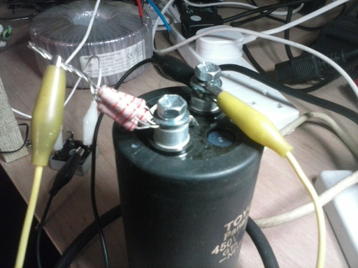
I filled in the values on the above circuit.
Testing on Real Batteries
Started with a relatively safe circuit which was extremely low current just to get a feel for the batteries reactionThis is a test which I expanded to charge 3 complete full batteries in parallel which were all very low.

Anyone who tells you that you need an expensive charger for Prius batteries just show them this :)
As the battery voltage rose I swapped out R1, R2 and R3 for 680 ohms (5w) at 200v
then 10 ohms (60w) at 280v and the batteries eventually rose to 320v.
200v is an average of 0.88v per cell.
280v is an average of 1.23v per cell.
320v is an average of 1.4v per cell.
Reading CHARGE METHODS FOR NICKEL METAL HYDRIDE BATTERIES it seems this was the best method for resurrecting these batteries.
"To charge excessively discharged or deep-discharged batteries, first allow a trickle current to flow,
and then proceed with the rapid charge current once the battery voltage has risen.
Rapid charge start voltage: Approx. 0.8V/cell
Rapid charge transition voltage restoration current: 0.2 ~ 0.3 CmA"
In this document it refers to "CmA" which is assuming the capacity (C) is in mAh.
This is indicating we should use a charge of C/5 to C/3.33.
Pretty much all these cells were well below the 0.8v, in fact alot would be 0v.
MCU Controlled PWM
Since, in a different project here MCU control of mains is actually quite easy and cheap,This can be extended using AC-DC then using an ADC to measure and control voltage.
So a first basic AC circuit driving a lamp was constructed:
This was adapted to DC with smoothing and symmetric cross detect:
Peak voltage across the LP1 was +320vDC on full and went to 0v.
PSUTest.ino
Also added a low power 5vDC supply for the Arduino.
This is OK, but R1 gets very hot.
A better way would be to use a PWM switch mode for the 5vDC too, using the resistor circuit to bootstrap.
Moving away from pure transformerless as this can be unstable.
Just using a small transformer for a simple PSU to power the Arduino.
Also updated to include sensor information and lower level software:
PSUTest.cpp
415vAC 3-phase
BIGGER FATTER WARNING!
These 3-phase MAINS, HIGH VOLTAGE experiments can kill you!
These 3-phase MAINS, HIGH VOLTAGE experiments can kill you!
The battery packs in the Mass-EV v0.1 are 3 x ~400vDC, so this will not charge from 240vAC even rectified to approx 330vDC.
In order to charge these a 3-phase charger using the 415vAC would be needed, unless we use a step-up transformer.
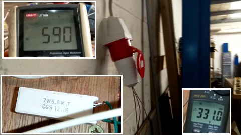
So 3-phase 415vAC UK mains rectifies to 587vDC.
To start with a primitive charge using a resistor dropdown:
This would take in the region of 1.5 months to charge from flat to full.
Really targeting something in the region of a week to be useful at the moment.
Which would be this:
This is a very basic charger, not really that cheap since it uses a £16 resistor.
But it's reliable would work at C/100.
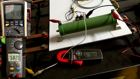
Top left is the pack voltage (418vDC) bottom left is the input voltage (583vDC) and you can see the current is 820mA.
The resistor is dissipating about 130W, well within the rated 200W.
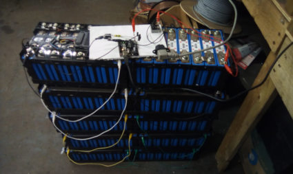
This was charging 32 x 12v 100Ah batteries (384vDC total), which of course was no problem.
Extending this to all 3 packs (99 batteries).
So to provide some degree of isolation the single 200Ω resistor was replaced with a pair of 100Ω resistors,
one to the positive terminal and one to the negative.
Also a pair of 100W/100Ω resistors are cheaper (~£5 each) than a single 200W/200Ω one.
Looking at testing an IGBT controlled PWM.
This is an untested triac design, which would be cheaper than IGBT.
This should provide up to 580vDC which means it would charge a 400vDC battery.
Charging from Domestic
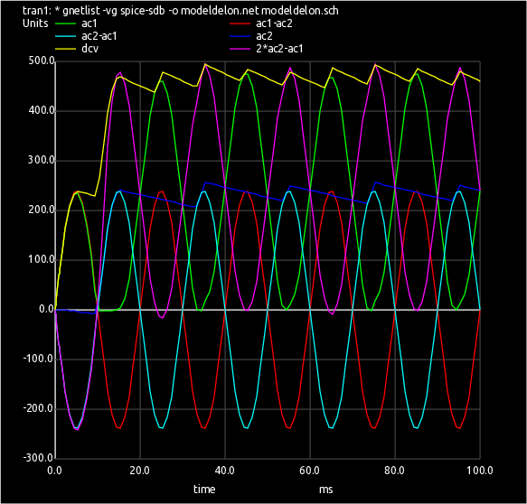
In order to charge a 415vDC battery from domestic UK mains the voltage first needs to be stepped up above the battery or it won't charge it.This can be done quite easily and cheaply using a voltage doubler circuit called a Delon circuit to give 680vDC
The diodes D3 and D4 (half the fullwave bridge) were left connected in parallel.
This was tested and gave a charge current of 1A, so equal to the 3 phase equivalent.
The 2700μF capacitors were swapped for 100μF and the current dropped to 0.75A, but was still charging so it was fine.
For US 110vAC (155Vp-p) a double Greinacher voltage quadrupler can be used to give 620vAC charging, again with a simple cheap circuit.
More Efficient Charging
Models
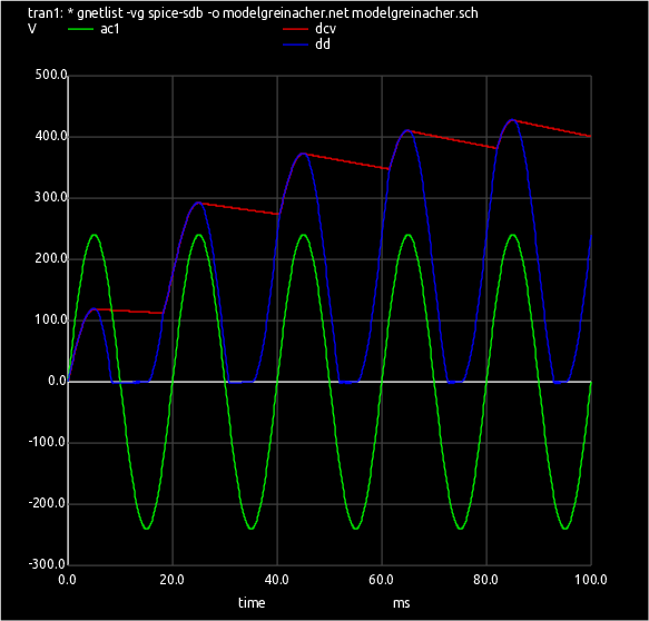
A practical charger using triac control and Delon doubler
This has been rigorously tested and is a good cheap efficient solution.
This charger reliably charges the high voltage battery for under £50 in parts

HVPSU.git
So this is the control interface of final charger:
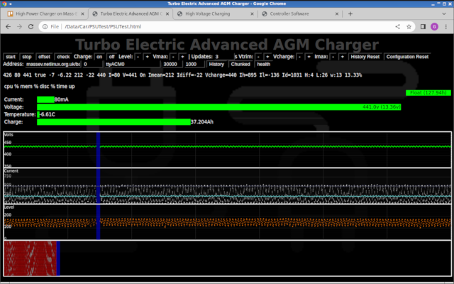
This has been tested for a considerable time now (approx 4 months continuously) under different SOC and initial conditions and has been found to be incredibly reliable.
Essentially the software monitors the voltage, current and temperature and implements a true 3-stage charger with over-volt and over-temp shut downs.
The interface shown above shows all the detail of the charging, including a historic plot of all parameters and even a heat map of TRIAC gate timing,
which is returned from the firmware as part of the JSON data.
The max current input to the battery (from UK 240vAC mains) is 6A which gives 16 hours flat-to-full charge time.
Each pack has it's own charger and mains plug so this means the whole car can be recharged from flat to full in 16h hours from standard mains outlets.
This is the only long range electric car in the world to do this.
All other cars require a special domestic outlet costing on average £500 or fast charge from a special commercial charging point.
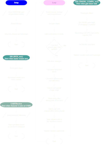
Flowcharts for the software

Upgrade For High Speed Charging
G-Wiz Charging
The battery in a G-Wiz is a simple 48v Lead Acid wet cell, so this doesn't need a sophisticated charger.This is just a 500w transformer, bridge and smoother and using a 10R/60W resistor for current limit.
Charge rate is about 1A into 200Ah battery so C/200.
The open circuit voltage is about 80v which is 3.33v per cell.
This can't be used for trickle charge as the gassing voltage is less than 2.5v per cell.
It would need to be limited to 60v for the pack for that which can be done with a LM317.
48v EV Motorbike charger
Using a purpose build charger from a 400va 48v transformer we get better results:
The secondary is 2 x 24vAC so in series is 48vAC.
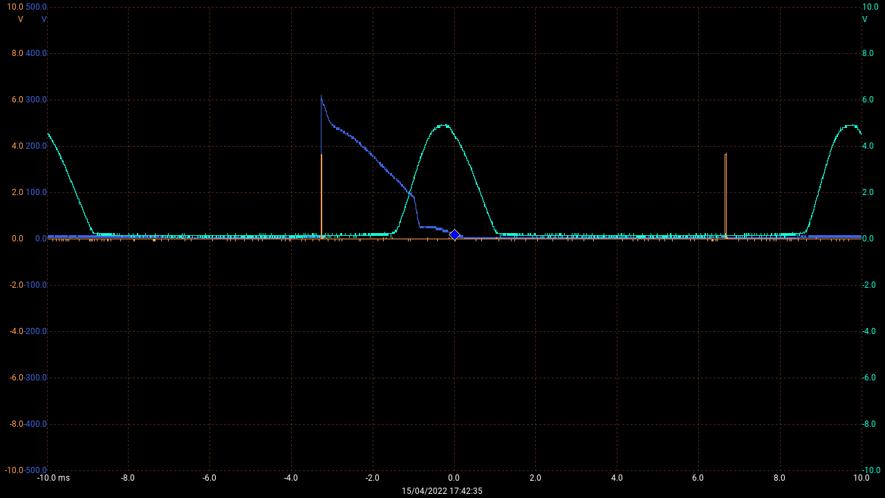
T1 secondary:
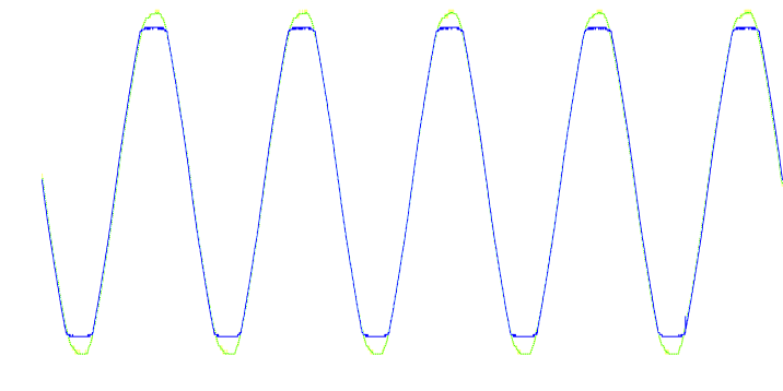
Yellow:open circuit, Blue:charging
The open circuit voltage is -78 to +77, so 77vAC amplitude which is 54v RMS
Charging this is reduced to -70 to +70, so 70vAC amplitude which is 50v RMS
Bridge rectifier got a bit hot so added a heatsink, and that cured it.
Charge rate is 5-10amps which is good enough for an overnight charger.
Voltage and Current Measurement
I acquired a battery which came from a Mitsubishi Outlander PHEV.This is a 300vDC battery with 80 x LEV40 lithium-ion (Li-ion) cells (not polymer: LiFePO4).
The cells are 40Ah and 3.5v-4.0v normal operation voltage with a max of 4.4v on full charge.
This means the pack is 40Ah x 300v = 12,000 Wh (12Kwh).
Volume of an 8 cell pack is 5.78l (175mm x 110mm x 300mm) which is 1.2kWh.
Volume of the 6-cell AGM battery used in the Mass-EV is 11.6l (211mm x 327mm x 168mm) and is also 1.2kWh (12v x 100Ah)
This is a proportion of 2.01:1 Li-ion vs AGM
So a battery for the Mass-EV in lithium-ion would be almost exactly half the size, but costs about 8 times the price (£110 vs £900 per battery)
It's worth pointing out that a Lithium Iron Phosphate (LiFePO4) pack is much bigger than lithium-ion (Li-ion). It would be about the same size as the AGM possible even slightly bigger.
So a trivial rectified mains charger was constructed which would charge the pack to a maximum of 330vDC (4.4v per cell).
Also this was an experiment in controlling the charge with a CPU.
LEV40Charger.git
The entire charger plus sensors would be around £20.
It charged at the rate of about 1A so would take 2 days to charge from flat.
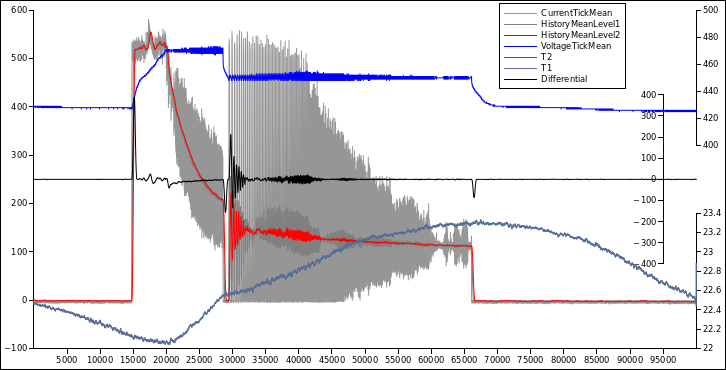
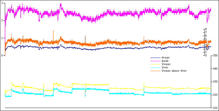
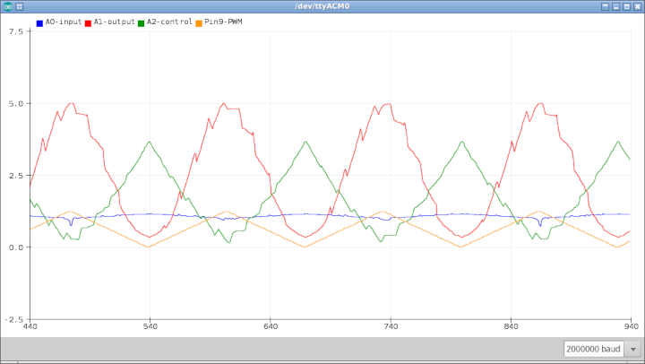
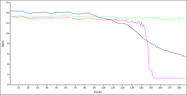
This is a table showing values calculated about every second.
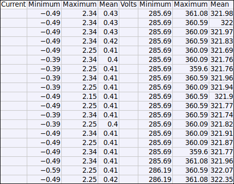
The current (blue) is expected to vary as it's only the tops of the recified mains which is actually pushing current into the battery.
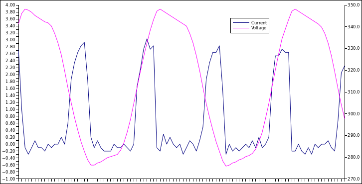
Reading current is OK but the voltage (purple) has way too much noise.
This is plot is over about 50mS at a resolution of about 500uS, voltage should be a flat line.
Revised the circuit to connect the CPU ground to the battery negative and the noise is gone.
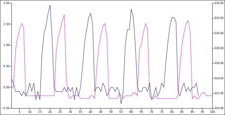
Now the voltage and current follow each other (with a bit of phase shift) which is how it should be.
BMS testing
This is an experiment using a small scale setup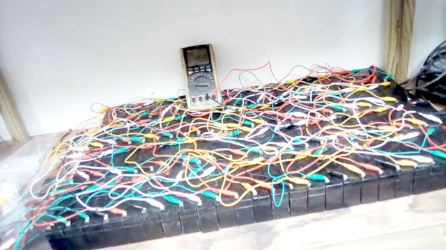


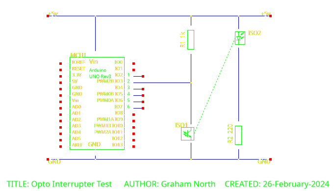
Testing the transfer of an optocoupler
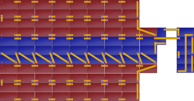
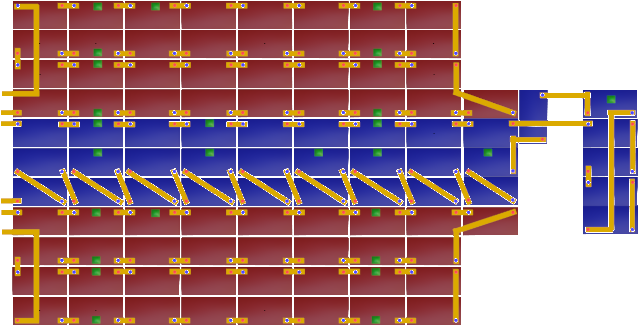
Mass-EV battery layout
AGM Charging
There is need of measuring the voltage of each 12v battery, but there are 99 of these so it must be something that scales cheaply.
Also it does not have to be extremely accurate as it's really just measuring the relative voltage against the pack voltage.
The most obvious way is to use an optocoupled circuit, so we need to check the accuracy of the optocoupler.
Optocouplers of the require quality cost 10p - 50p, a 1k resistor is less than a penny, and the Arduino Mega is from £13 - £35 which should manage the whole pack.
This means we can monitor the whole pack with less than £100 of components.
Wiring would be a considerable cost, but again should be within that budget.
The downside is that this will draw a small current constantly.
Up to 15vDC in the circuit, minus the voltage drop across the optocoupler LED (1v) would be across the 1k resistor.
I = V / R
I = 14v / 1k
I = 14mA
Also need to know the power is withing spec of the resistor:
P = V2 / R
P = (14v)2 / 1k
P = 0.196w
So a 1/4w cheap resistor would be fine
This is across an 100Ah battery so if this was the only thing draining it the time for full discharge would be:
t = Q / I
t = 100Ah / 14mA
t = 7142.86 hours
t = 297.62 days
...so nearly a year.
Also we need a circuit which will cope with the full range of the 12v battery.
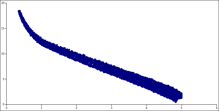
So this looks like it gives about 10% error for any single reading.
If this uses multiple samples and averages then this would be brought down considerably.
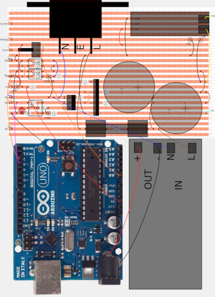
Real Life Testing
This is now hooked up to a small scale pack of 6v batteries on charge as a pack.
A0 and A1 were 12v (2 batteries in series), and A2 and A3 were on 6v singles.
The check was run over a few hours with a very rough recified mains charger attached.
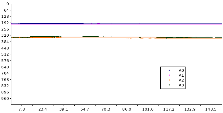
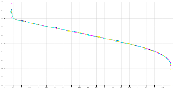
This is the raw ADC input 0<=ADC<=1023 which needs the mapping graph above to get the voltages where 5v output = 1023.
The values are roughly 200 and 340, so 0.97v and 1.66v which map to about 14v and 10v.
These are shifted because the collector resistor is different: 470R vs 300R,
but it very obviously measures the batteries independently and seems quite stable.
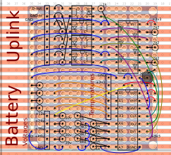
BMS Module
These modules are completely isolated from the manager and take their power from the batteries they are measuring directly.In an EV they would, of course, be doing this anyway just indirectly through the 12v system which is powered from the same batteries.
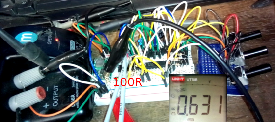
The amount of current drawn from the battery is 0.631v / 100R = 6.31mA (I = V / R),
which means for a 100Ah battery it will take 100,000mAh / 6.31mA = 15848 hours (=1.81 years) to discharge it.
Single
This doubles up the voltage and temperature measurements for greater accuracy.
4 battery serial string
This is the same as the above one, but using the 8 ADC inputs to measure voltage and temperature of 4 batteries in series.
It sacrifices some accuracy to use 27 modules instead of 100.
This basically uses a small analogue computer circuit to subtract the voltage and then divide what's left so it brings it in the range of the ADC inputs.
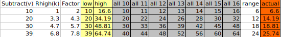
Improved range and accuracy.
This (above) uses single zeners and resistors which is more practical in a module,
and more accurate as the tolerance is just for a single component instead of many combined.
The reality is the accuracy will be good enough with single probes which is the same as all other EV and hybrid car systems.
Layout for modules on perfboard.
Experimental interface written for a browser.
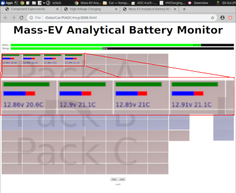
The first 4 batteries of pack A are returning realtime voltage and temperature.
LV Power
12v system
All current electric cars have an auxiliary 12v battery which is prone to going flat.Even a Tesla has this auxiliary 12v battery system.
In our car the 12v comes directly from the traction battery, so no "going flat" problems.
You can leave the lights on for like a year and the car will still run.
So here we have a 360w DC-DC converter which uses a flyback converter to convert 420vDC to 12vDC.
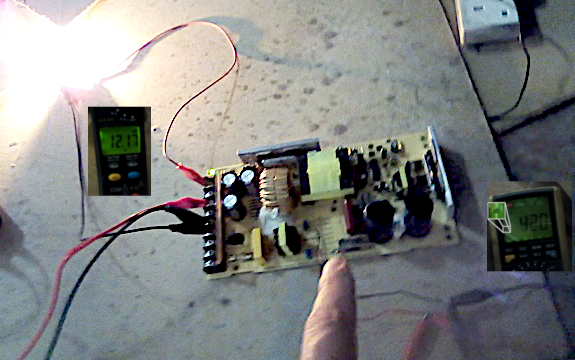
The output of this is an isolated 12vDC at 30amps, for an input current of less than 1 amp from the traction battery at full power.
These are very efficient (approx 80%) and, given that these form the basis of most modern mains power packs, are very reliable.
The car will have 3 of these (one for each traction battery) so the combined power will be over 1kW at 12vDC.
Obviously triply redundant as well, and will provide a good solid 12vDC even when the traction battery is far too flat to power the car.
In the circuit are also a local 5vDC buck converter to provide 5vDC at 3A.
So no need for an auxiliary battery which is prone to going flat in less than a day.
5v system
Also there are some 5vDC systems in the car (Raspberry Pi and Arduino).These get their power by dropping the power from 12vDC to 5vDC using a buck converter circuit.
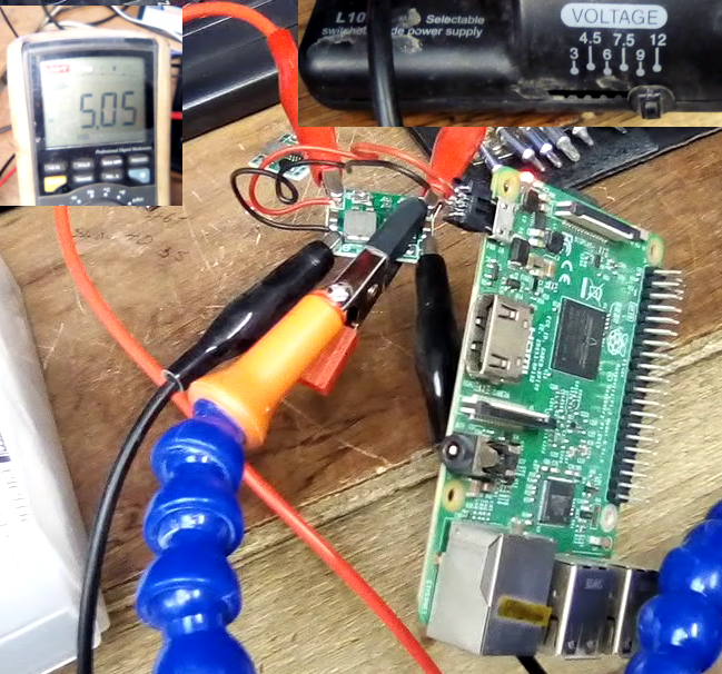
Again very efficient >85% and high output (3A).
So there will be plenty of high power USB charging points in the car.