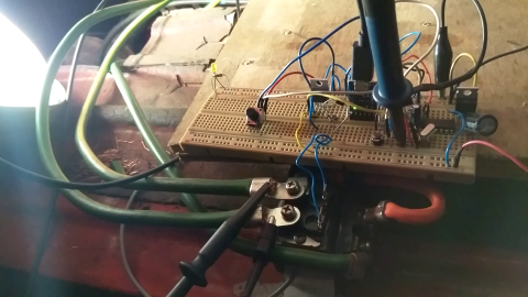
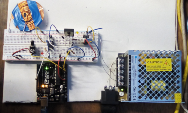
Component Experiments
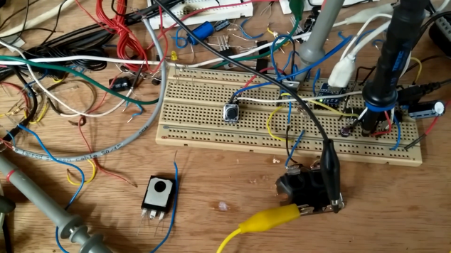
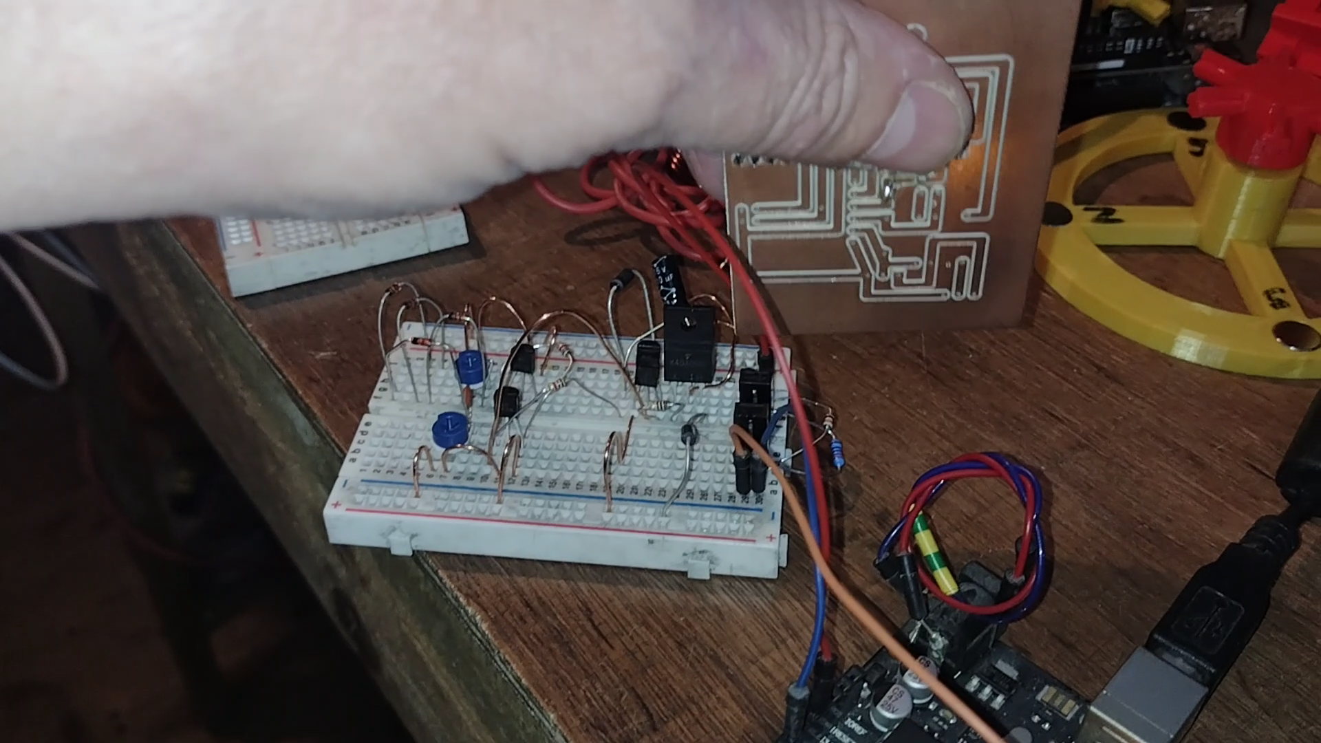
Simple Test of Optocoupler and IGBT
Simple test of new FGA50S110P and 6N136:


const int sensorPin = A0;
const int ledPin = 13;
const int sensorFactor = 5;
const int sensorLimit = 1024 >> sensorFactor;

void setup()
{
  pinMode (ledPin, OUTPUT);
}

void loop()
{
  int sensorValue = analogRead (sensorPin) >> sensorFactor;

  digitalWrite (ledPin, HIGH);

  delay (sensorValue);

  digitalWrite (ledPin, LOW);

  delay (sensorLimit-sensorValue);
}
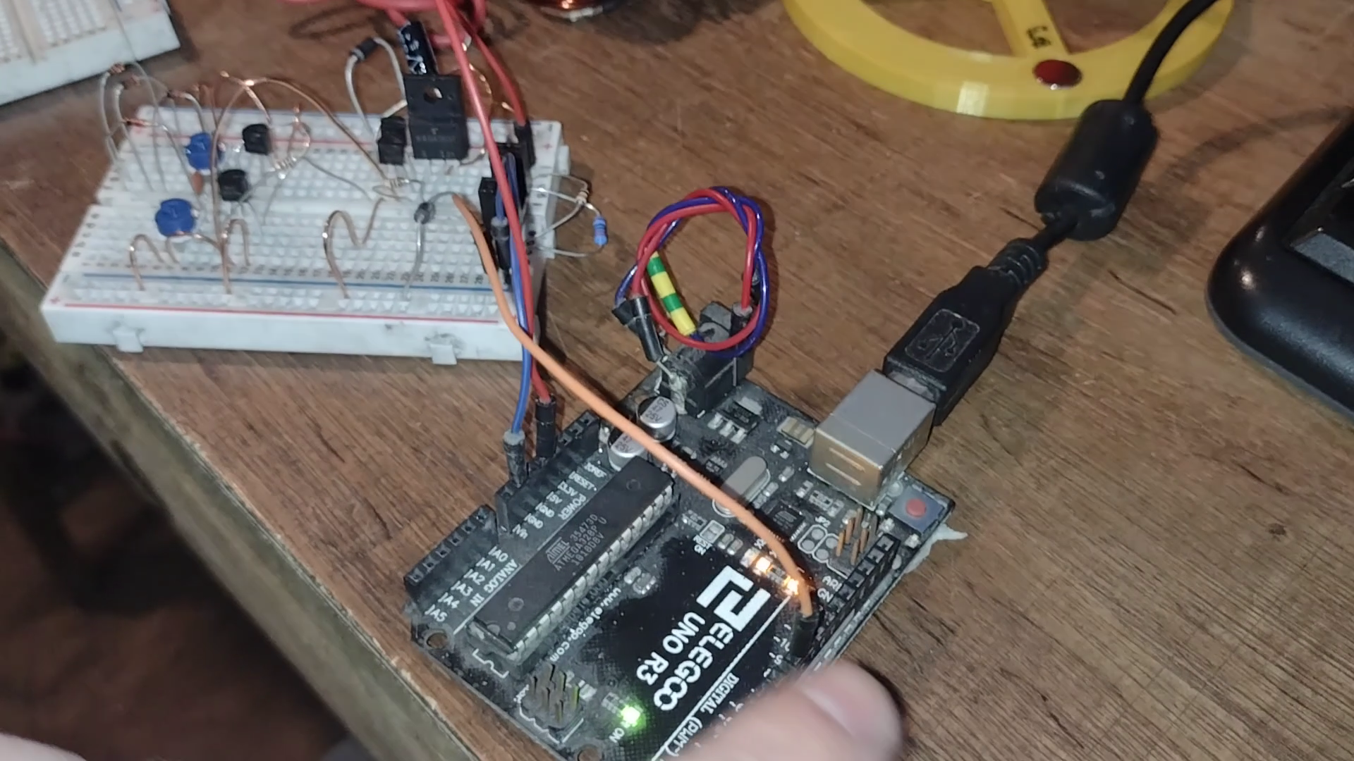
Using Current Amplifier for Gate

const int sensorPin = A0;
const int ledPin = 13;
const int sensorFactor = 5;
const int sensorLimit = 1024 >> sensorFactor;

const int TEMPLIMIT = 700;
const int TEMPSAFE = 600;

int sensorValue = 0;
int OverTemp = 0;

void setup()
{
  pinMode (ledPin, OUTPUT);

  Serial.begin (115200);
}

void loop()
{
  int TempSensor = analogRead (A1);

  Serial.print (TempSensor);
  Serial.print ('\t');

  sensorValue = analogRead (sensorPin) >> sensorFactor;

  Serial.print (sensorValue);

  if (TempSensor < TEMPLIMIT && (!(OverTemp) || TempSensor < TEMPSAFE))
  {
      digitalWrite (ledPin, HIGH);

      delay (sensorValue);

      digitalWrite (ledPin, LOW);

      delay (sensorLimit-sensorValue);

      OverTemp = 0;
  }
  else
  {
      digitalWrite (ledPin, LOW);

      OverTemp = 1;
  }

  Serial.print ('\n');
}
const int sensorPin = A0;
const int ledPin = 13;
const int sensorFactor = 5;
const int sensorLimit = 1024 >> sensorFactor;

const int TEMPLIMIT = 800;
const int TEMPHIGH = 750;
const int TEMPSAFE = 750;

int sensorValue = 0;
int OverTemp = 0;

void setup()
{
  pinMode (ledPin, OUTPUT);

  Serial.begin (115200);
}

void loop()
{
  int TempSensor = analogRead (A1);

  Serial.print (TempSensor);
  Serial.print ('\t');

  sensorValue = analogRead (sensorPin) >> sensorFactor;

  if (TempSensor > TEMPHIGH)
  {
      sensorValue -= ((TempSensor - TEMPHIGH) >> 2);

      if (sensorValue < 0)
          OverTemp = 1;
  }

  Serial.print (sensorValue);

  if (TempSensor < TEMPLIMIT && (!(OverTemp) || TempSensor < TEMPSAFE))
  {
      digitalWrite (ledPin, HIGH);

      delay (sensorValue);

      digitalWrite (ledPin, LOW);

      delay (sensorLimit-sensorValue);

      OverTemp = 0;
  }
  else
  {
      digitalWrite (ledPin, LOW);

      OverTemp = 1;
  }

  Serial.print ('\n');
}

  if (TempSensor < TEMPLIMIT && (!(OverTemp) || TempSensor < TEMPSAFE))
  {
      digitalWrite (ledPin, HIGH);

      delayMicroseconds (sensorValue);

      digitalWrite (ledPin, LOW);

      delayMicroseconds (sensorLimit-sensorValue);

      OverTemp = 0;
  }
  else
  {
      digitalWrite (ledPin, LOW);

      OverTemp = 1;
  }
Using Higher Gain Current Amplifier


const int TEMPLIMIT = 800;

const int CONTROLINPUT = A0;
const int TEMPINPUT    = A1;
const int MOTOROUTPUT  = 13;

const int TEMPHIGH    = 800;
const int TEMPSAFE    = 700;

int ControlInput = 0;
int TempInput = 0;
int MotorOutput = 0;
int TempHigh = 0;

void setup()
{
  Serial.begin(115200);
}

void loop()
{
  ControlInput = analogRead(CONTROLINPUT);
  TempInput = analogRead(TEMPINPUT);

  MotorOutput = map(ControlInput, 0, 1023, 0, 255);

  if (TempHigh)
  {
      if (TempInput < TEMPSAFE)
          TempHigh = 0;

      analogWrite(MOTOROUTPUT, 0);
  }
  else
  {
      if (TempInput > TEMPHIGH)
          TempHigh = 1;

      analogWrite(MOTOROUTPUT, MotorOutput);
  }

  Serial.print("ControlInput = " );
  Serial.print(ControlInput);
  Serial.print("\tTempInput = " );
  Serial.print(TempInput);
  Serial.print("\t MotorOutput = ");
  Serial.println(MotorOutput);

  delay(100);
}
ControlInput = 291	TempInput = 770	 MotorOutput = 72
ControlInput = 292	TempInput = 770	 MotorOutput = 72
ControlInput = 286	TempInput = 770	 MotorOutput = 71
ControlInput = 291	TempInput = 777	 MotorOutput = 72
ControlInput = 288	TempInput = 769	 MotorOutput = 71
ControlInput = 290	TempInput = 770	 MotorOutput = 72
ControlInput = 290	TempInput = 770	 MotorOutput = 72
ControlInput = 288	TempInput = 770	 MotorOutput = 71
ControlInput = 290	TempInput = 769	 MotorOutput = 72
ControlInput = 290	TempInput = 769	 MotorOutput = 72
ControlInput = 290	TempInput = 769	 MotorOutput = 72
ControlInput = 291	TempInput = 769	 MotorOutput = 72
ControlInput = 290	TempInput = 770	 MotorOutput = 72
ControlInput = 290	TempInput = 769	 MotorOutput = 72
ControlInput = 293	TempInput = 769	 MotorOutput = 73
ControlInput = 290	TempInput = 769	 MotorOutput = 72
ControlInput = 291	TempInput = 768	 MotorOutput = 72
ControlInput = 291	TempInput = 768	 MotorOutput = 72
ControlInput = 290	TempInput = 769	 MotorOutput = 72
ControlInput = 288	TempInput = 768	 MotorOutput = 71
ControlInput = 290	TempInput = 769	 MotorOutput = 72
ControlInput = 288	TempInput = 770	 MotorOutput = 71
ControlInput = 290	TempInput = 769	 MotorOutput = 72
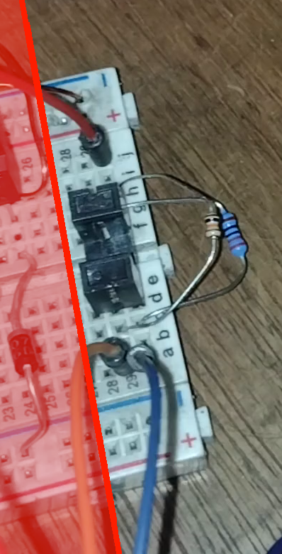
Higher Speed Optocouplers
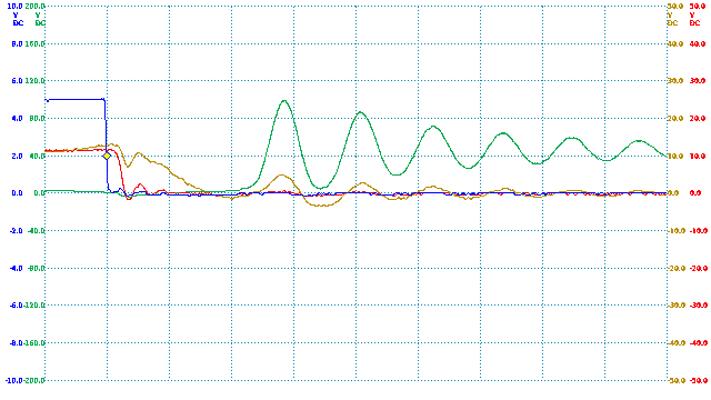
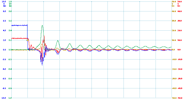
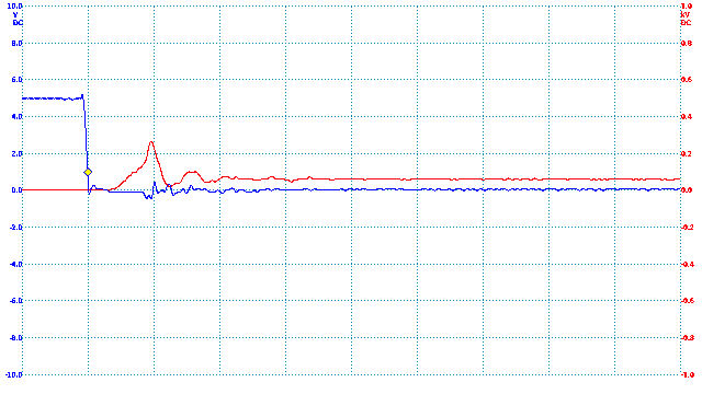
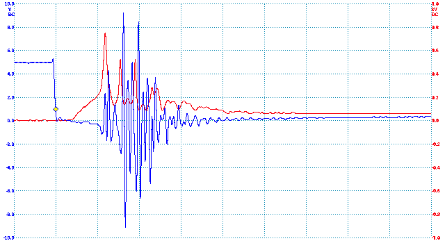
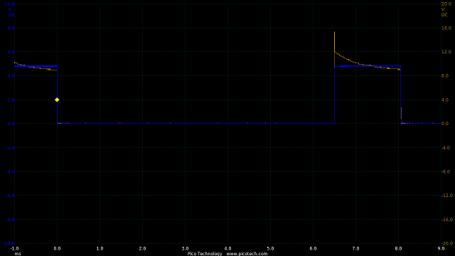
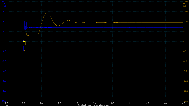
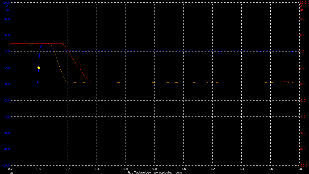
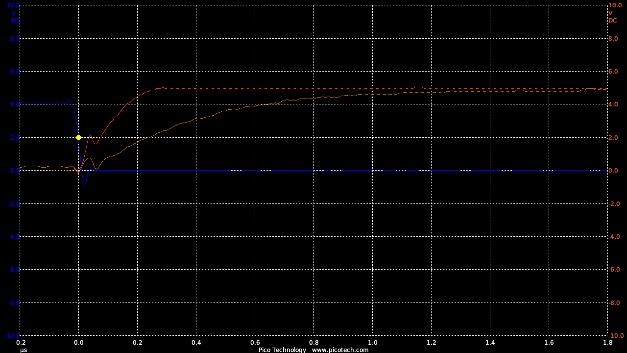
This is a test of the 6N136 in inverting mode.
The test is done both without then with the biasing resistor (R3)
Red without R3, Orange with R3
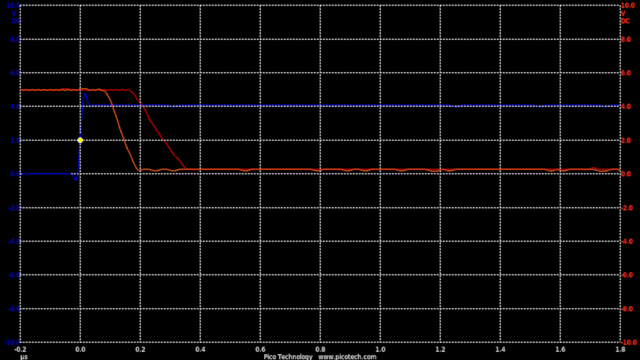
TIME:200nS/div, Blue:TP1(2vDC/div), Red:TP2+R3(2vDC/div), Orange:TP2-R3(2vDC/div).
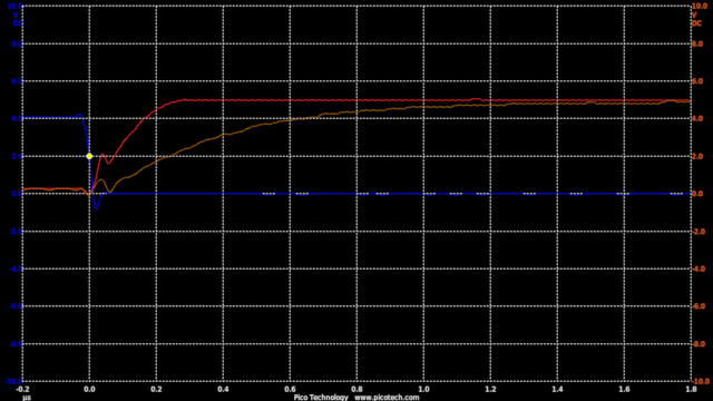
TIME:200nS/div, Blue:TP1(2vDC/div), Red:TP2+R3(2vDC/div), Orange:TP2-R3(2vDC/div).
The effect of the biasing resistor is to speed up the switch off at the cost of switch on time.
In the circuit a 10k resistor added means the rise and fall times are now roughly equal at 200nS
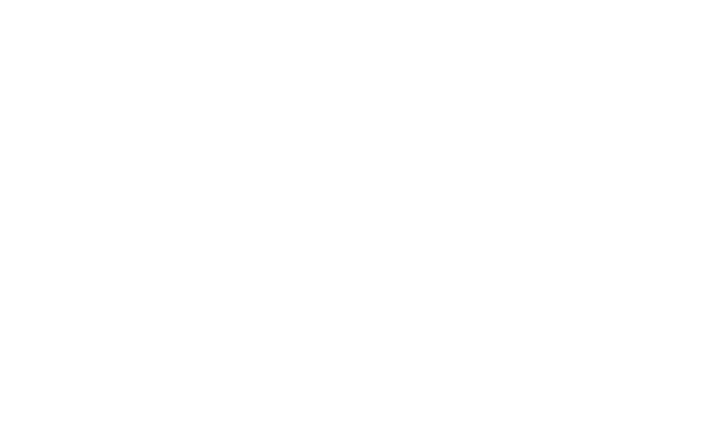
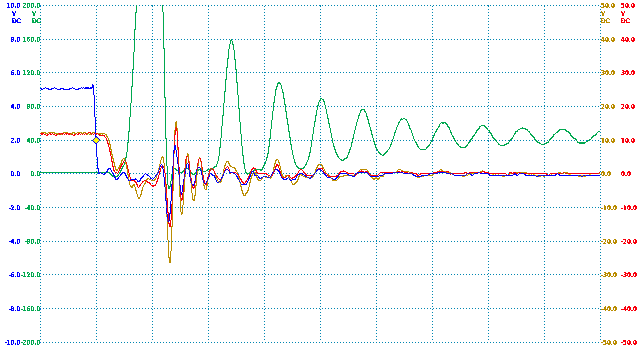
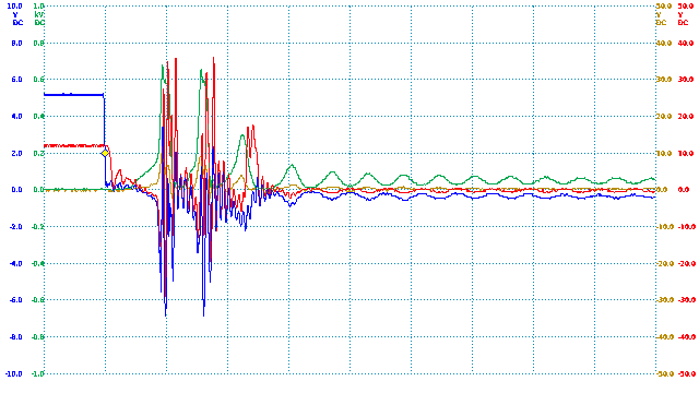
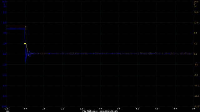
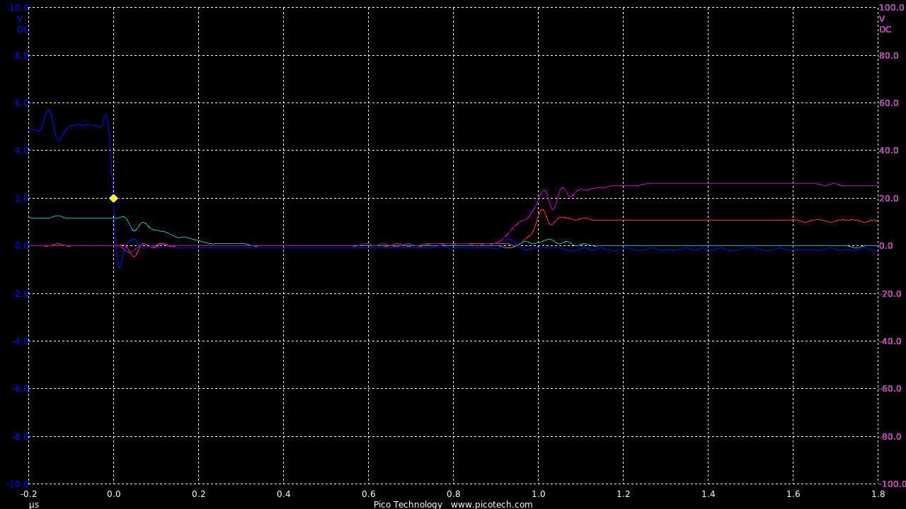
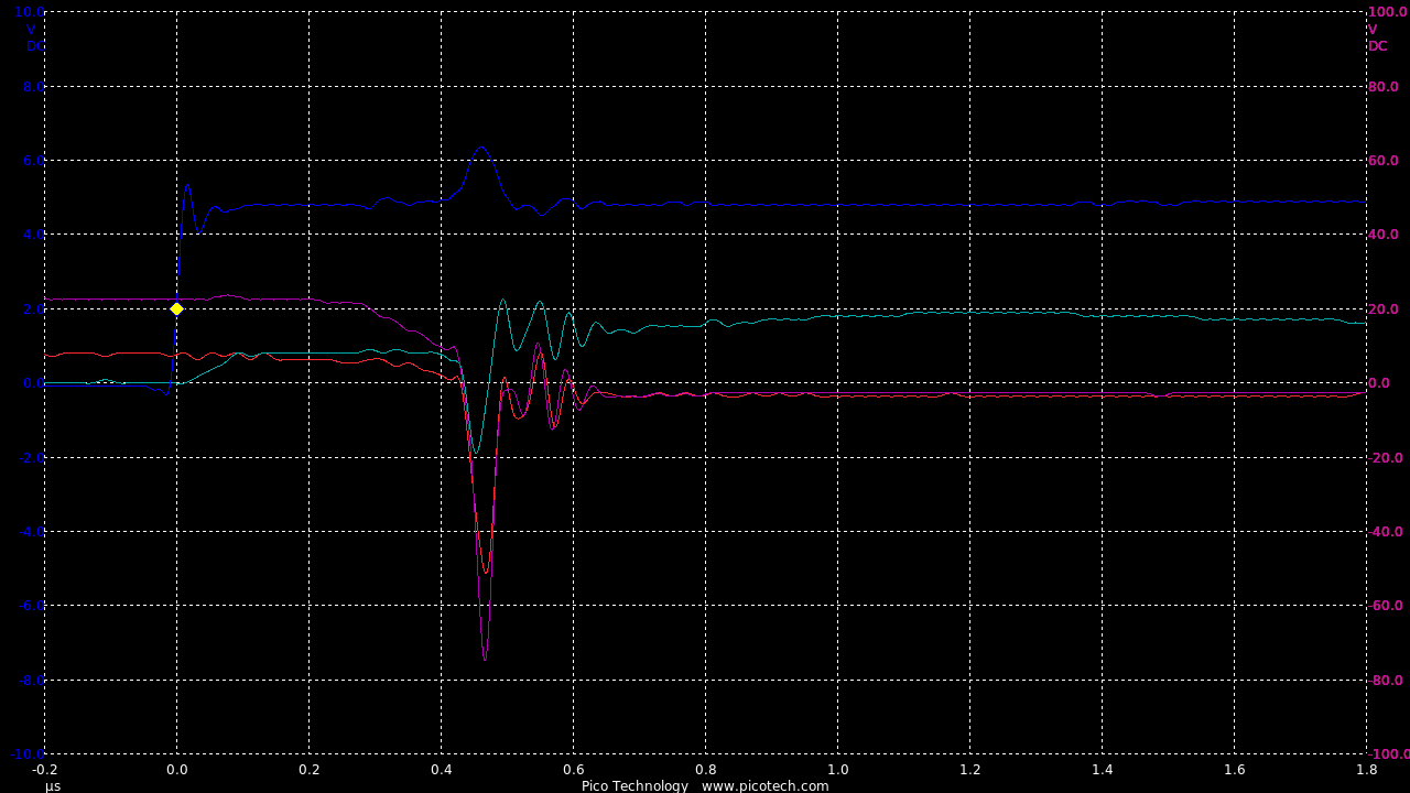
Add the trinary circuit, also using a DC-DC converter for high side gate supply
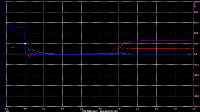
TIME:200nS/div, Blue:TP1(2vDC/div), Red:TP5(20vDC/div), Magenta:TP3(20vDC/div), Cyan:TP4(20vDC/div).
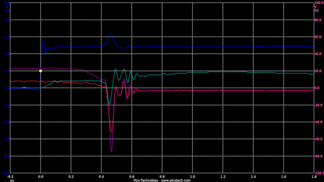
TIME:200nS/div, Blue:TP1(2vDC/div), Red:TP5(20vDC/div), Magenta:TP3(20vDC/div), Cyan:TP4(20vDC/div).
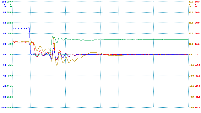
Using Two NPN IGBTs in Push-Pull

Direct Coupling of the MCU


Thermistor Reading
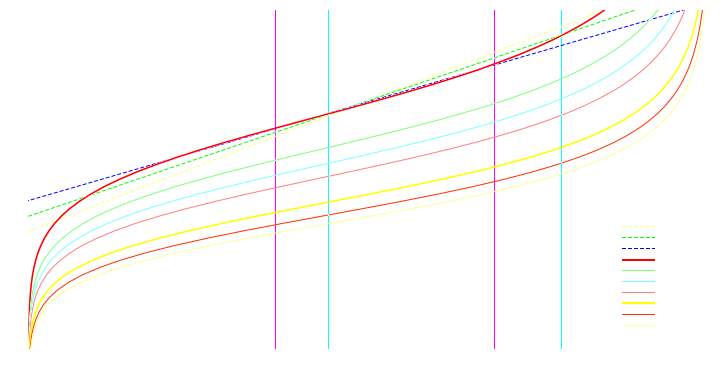
Thermister transfer plots for different lowside loads and linear approximations:
const int CONTROLINPUT = A0;
const int TEMPINPUT    = A1;
const int MOTOROUTPUT  = 11;
const int MOTOROFF     = 255;

const int TEMPHIGH    = 450;
const int TEMPSAFE    = 370;

int ControlInput = 0;
int TempInput = 0;
int TempInC = 0;
int MotorOutput = 0;
int TempHigh = 0;

void setup()
{
  Serial.begin(115200);
  Serial.println("Grahams Motor Test, "__DATE__" ("__TIME__")");
}

void loop()
{
  ControlInput = analogRead(CONTROLINPUT);
  TempInput = analogRead(TEMPINPUT);

// For 1k lowside: 45C < Temp ~ +-1C < 112C
  TempInC = (TempInput * 10 / 76) + 21;

  if (TempInput < TEMPSAFE)
      TempHigh = 0;

  if (TempInput > TEMPHIGH)
      TempHigh = 1;

  MotorOutput = ControlInput >> 2;

  if (TempHigh)
      analogWrite(MOTOROUTPUT, MOTOROFF);
  else
      analogWrite(MOTOROUTPUT, MotorOutput);

  Serial.print("ControlInput = " );
  Serial.print(ControlInput);
  Serial.print("\tTempInput = " );
  Serial.print(TempInput);
  Serial.print("(");
  Serial.print(TempInC);
  Serial.print("C)\tMotorOutput = ");
  Serial.println(MotorOutput);

  delay(100);
}
Grahams Motor Test, Apr 20 2016 (12:12:09)
ControlInput = 892	TempInput = 165(42C)	MotorOutput = 223
ControlInput = 891	TempInput = 165(42C)	MotorOutput = 222
ControlInput = 891	TempInput = 166(42C)	MotorOutput = 222
ControlInput = 892	TempInput = 165(42C)	MotorOutput = 223
ControlInput = 891	TempInput = 165(42C)	MotorOutput = 222
ControlInput = 892	TempInput = 162(42C)	MotorOutput = 223
ControlInput = 891	TempInput = 165(42C)	MotorOutput = 222
ControlInput = 891	TempInput = 165(42C)	MotorOutput = 222
ControlInput = 891	TempInput = 165(42C)	MotorOutput = 222
ControlInput = 892	TempInput = 164(42C)	MotorOutput = 223
ControlInput = 891	TempInput = 165(42C)	MotorOutput = 222
ControlInput = 892	TempInput = 164(42C)	MotorOutput = 223
ControlInput = 891	TempInput = 160(42C)	MotorOutput = 222
ControlInput = 891	TempInput = 164(42C)	MotorOutput = 222
ControlInput = 891	TempInput = 164(42C)	MotorOutput = 222
ControlInput = 891	TempInput = 166(42C)	MotorOutput = 222
ControlInput = 891	TempInput = 164(42C)	MotorOutput = 222
ControlInput = 891	TempInput = 165(42C)	MotorOutput = 222
ControlInput = 891	TempInput = 155(41C)	MotorOutput = 222
ControlInput = 891	TempInput = 165(42C)	MotorOutput = 222
ControlInput = 892	TempInput = 164(42C)	MotorOutput = 223
ControlInput = 892	TempInput = 165(42C)	MotorOutput = 223
ControlInput = 891	TempInput = 165(42C)	MotorOutput = 222
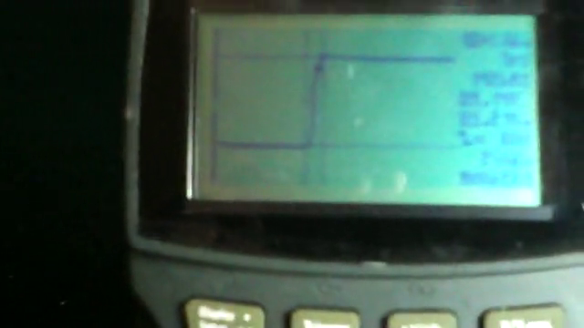
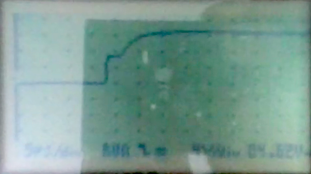
Rise time about 10uS:
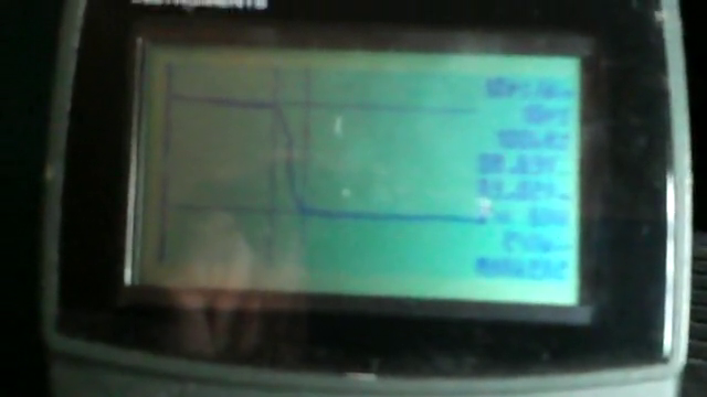
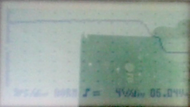
Fall time about 10uS:
Someone from the Arduino Community has coded a conversion algorithm for the thermistor setup used above [link].
A comparison graph for different low-side resistors against the ND03N00103J is here:
This verifies the use of the 1k low-side (cyan) and means we can now refine the temperature readings.
High Side

Low Side


Gate charging with a current source


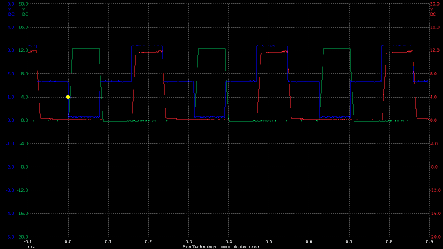
Rise time in the order of 10uS:
Fall time in the order of 1uS:
Adding current amplifier for gate


Rise time is about 4uS:
Fall time is about 500nS:
Continued on Controller Software, Modelling and Tuning and Field Control
Latest version of DueTest.cpp:
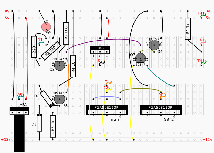
MicroChip Driver IC
Sourced a new driver chip made by Microchip:

Constructed a simple test to see if it works.
Seems to work quite well.
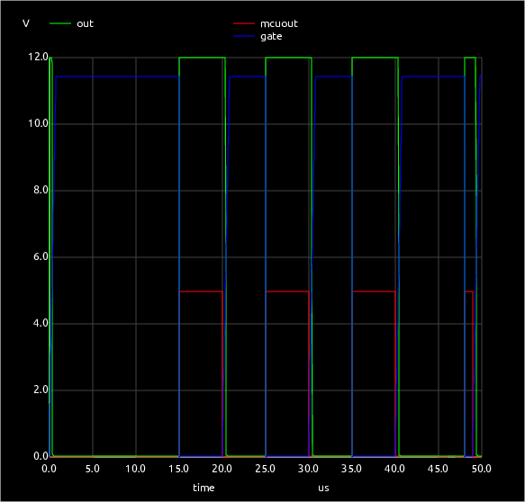
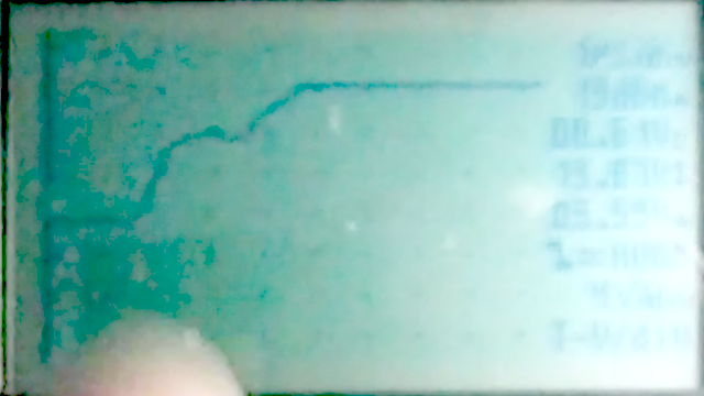
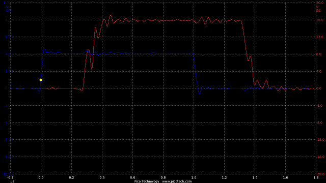
Below is a test as 62.5kHz.
TIME:2uS/div, Blue:TP1(2vDC/div), Red:TP2(4vDC/div), Green:TP3(10vCD/div).
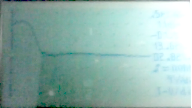
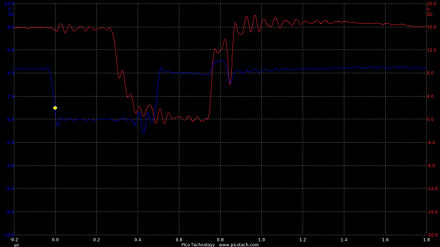
..and tested with 320A IGBT (IXGN320N60A3)
TIME:2uS/div, Blue:TP1(2vDC/div), Red:TP2(4vDC/div), Green:TP3(10vDC/div).
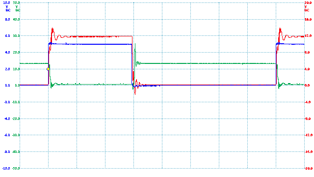
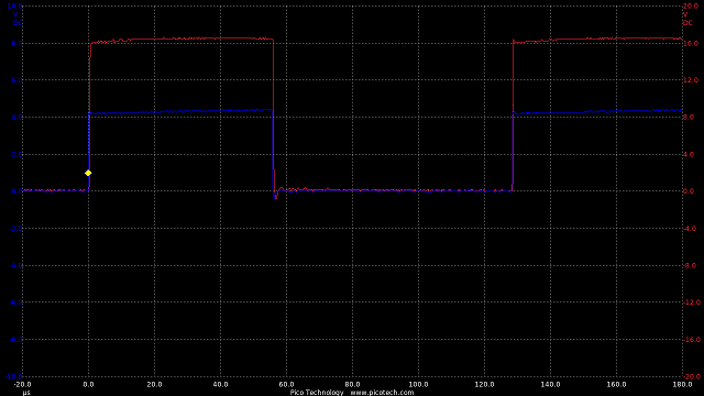
From these test it seems the driver chip is working in the nanosecond switching range with the low power motor switching within a microsecond too.
Short switch testing shows we can have sub-microsecond PWM mark and space.
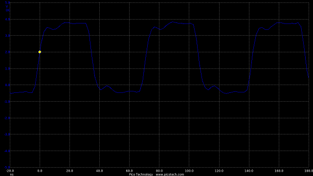
TIME:500nS/div, Blue:TP1(2vDC/div), Red:TP2(4vDC/div), Green:TP3(10vDC/div).
TIME:500nS/div, Blue:TP1(2vDC/div), Red:TP2(4vDC/div), Green:TP3(10vDC/div).
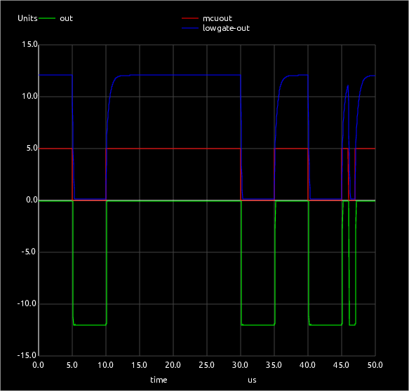
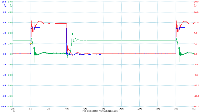
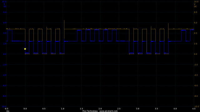
Seems to work OK until a low frequency PWM is used.
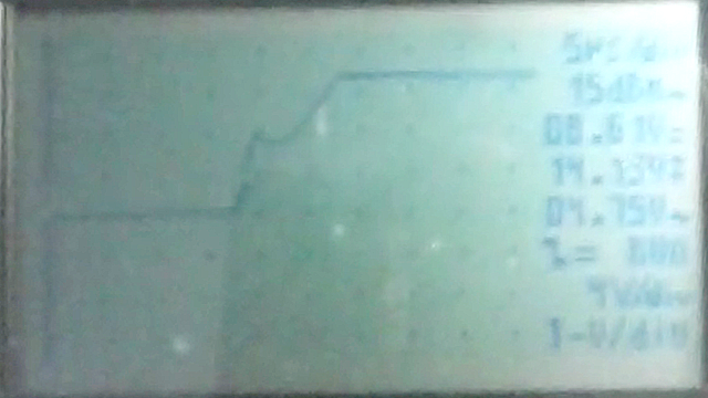
This show the switch to space at 30Hz:
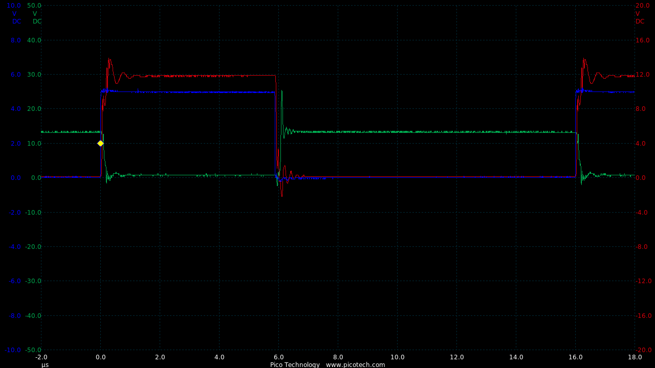
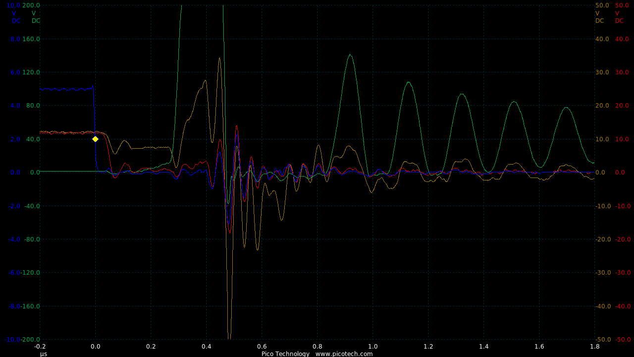
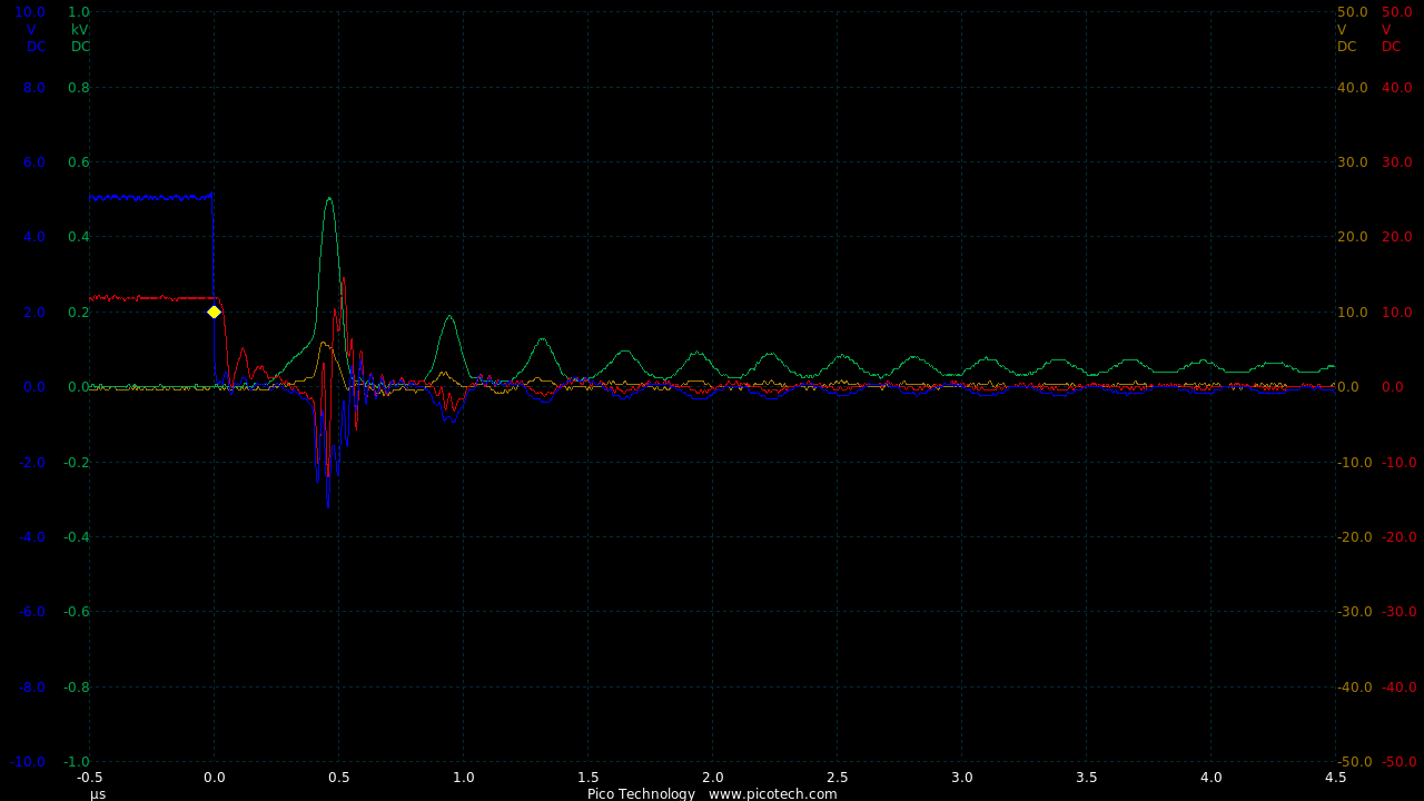
TIME:200nS/div, Blue:TP1(2vDC/div), Red:TP2(10vDC/div), Green:TP3(40vDC/div), Orange:Gate(10vDC/div).
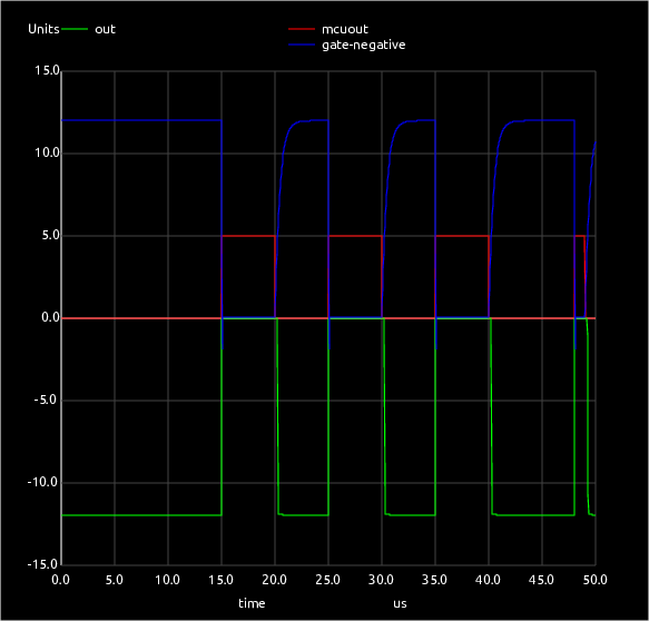
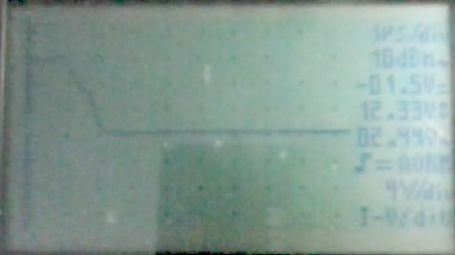
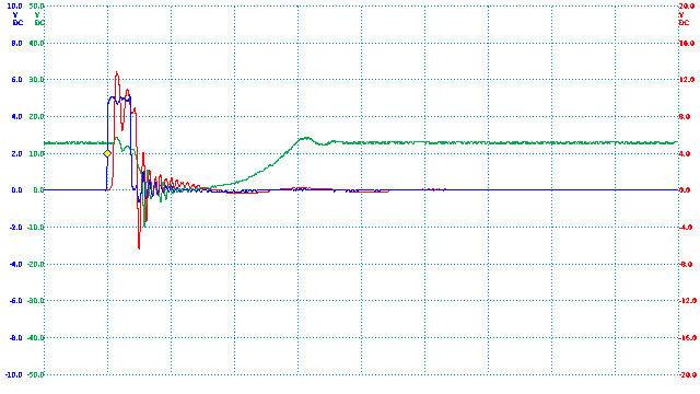
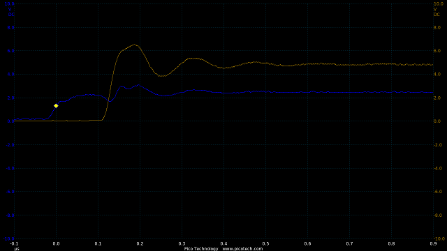
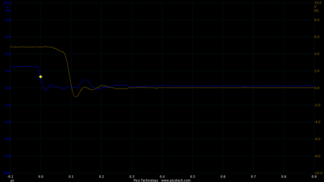
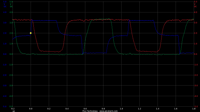
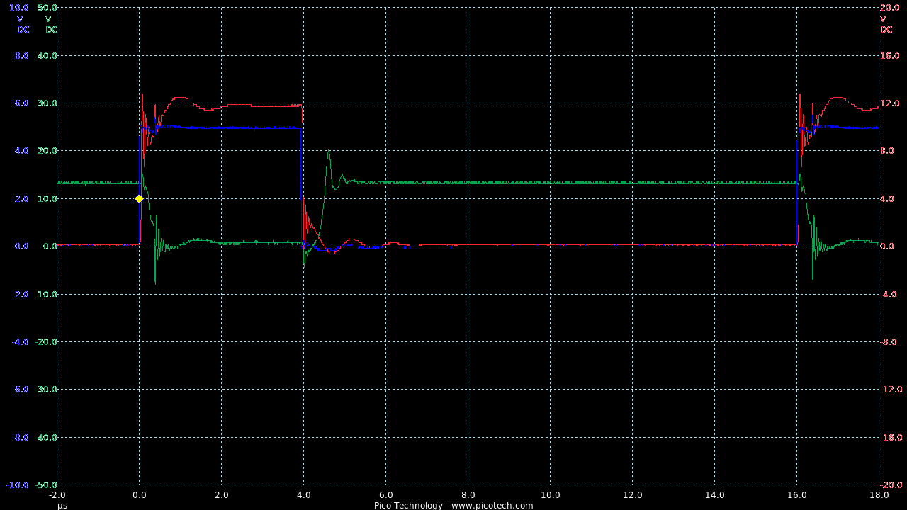
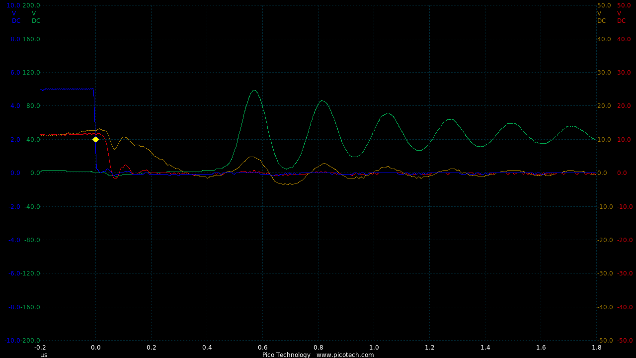
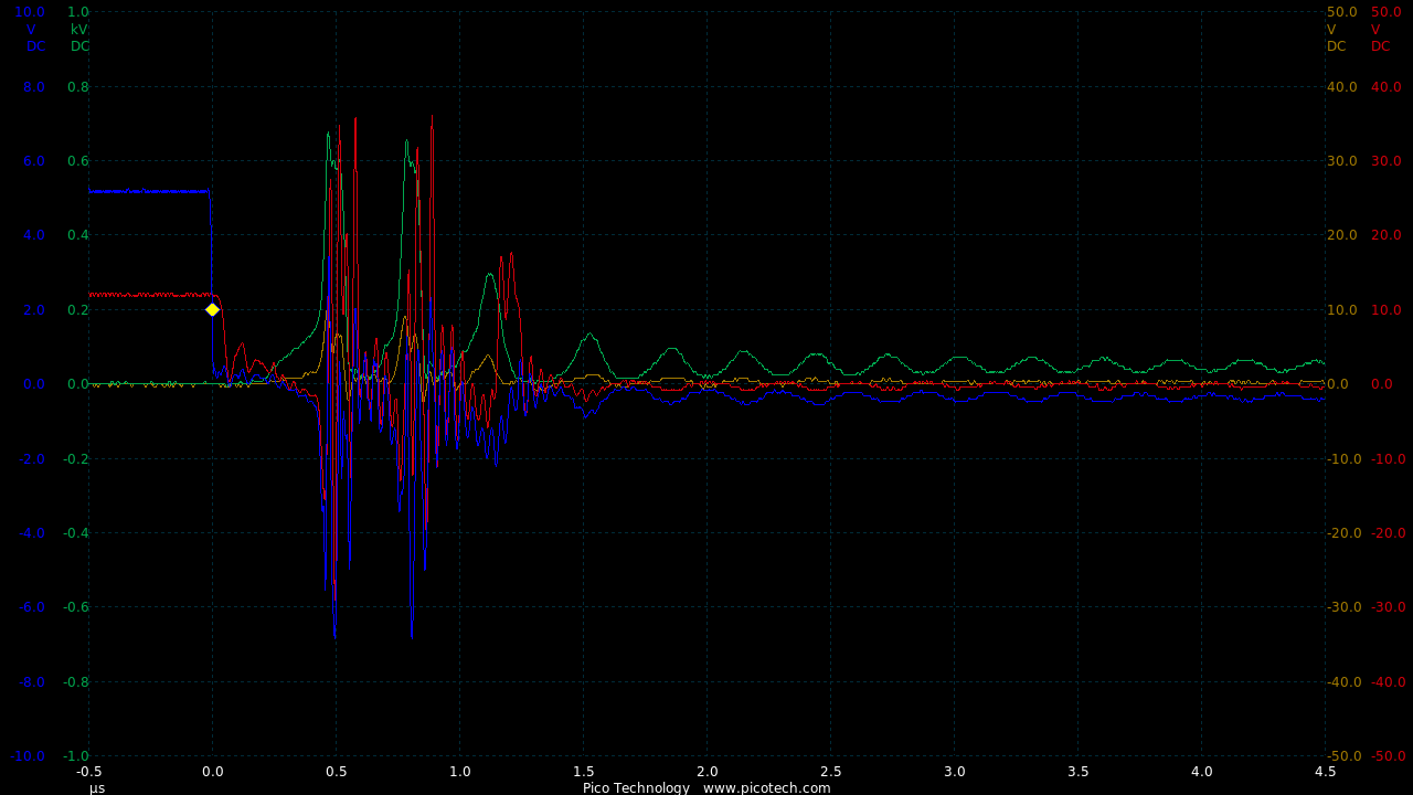
At higher frequencies (4kHz) the signal is much better:
TIME:200nS/div, Blue:TP1(2vDC/div), Red:TP2(10vDC/div), Green:TP3(40vDC/div), Orange:Gate(10vDC/div).
Unfortunately, this voltage spike (+30v/-50v, above) on the gate is beyond the specification of the IGBT (+-20v), which causes it to blow.
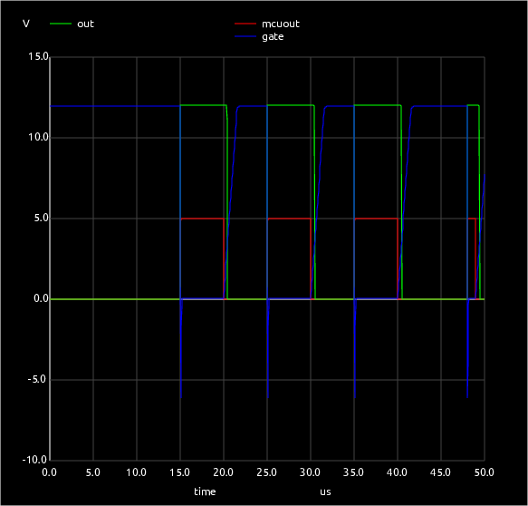
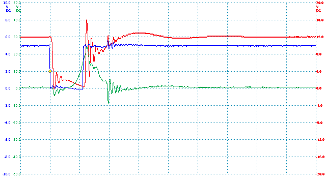
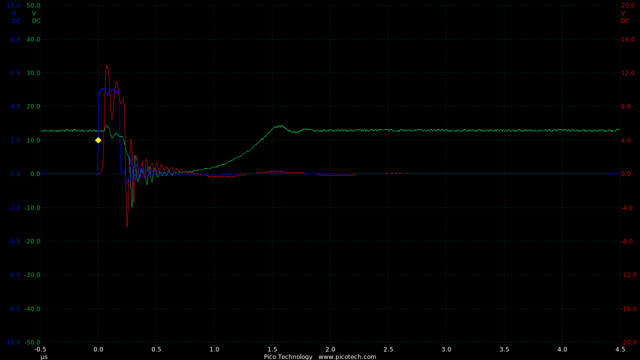
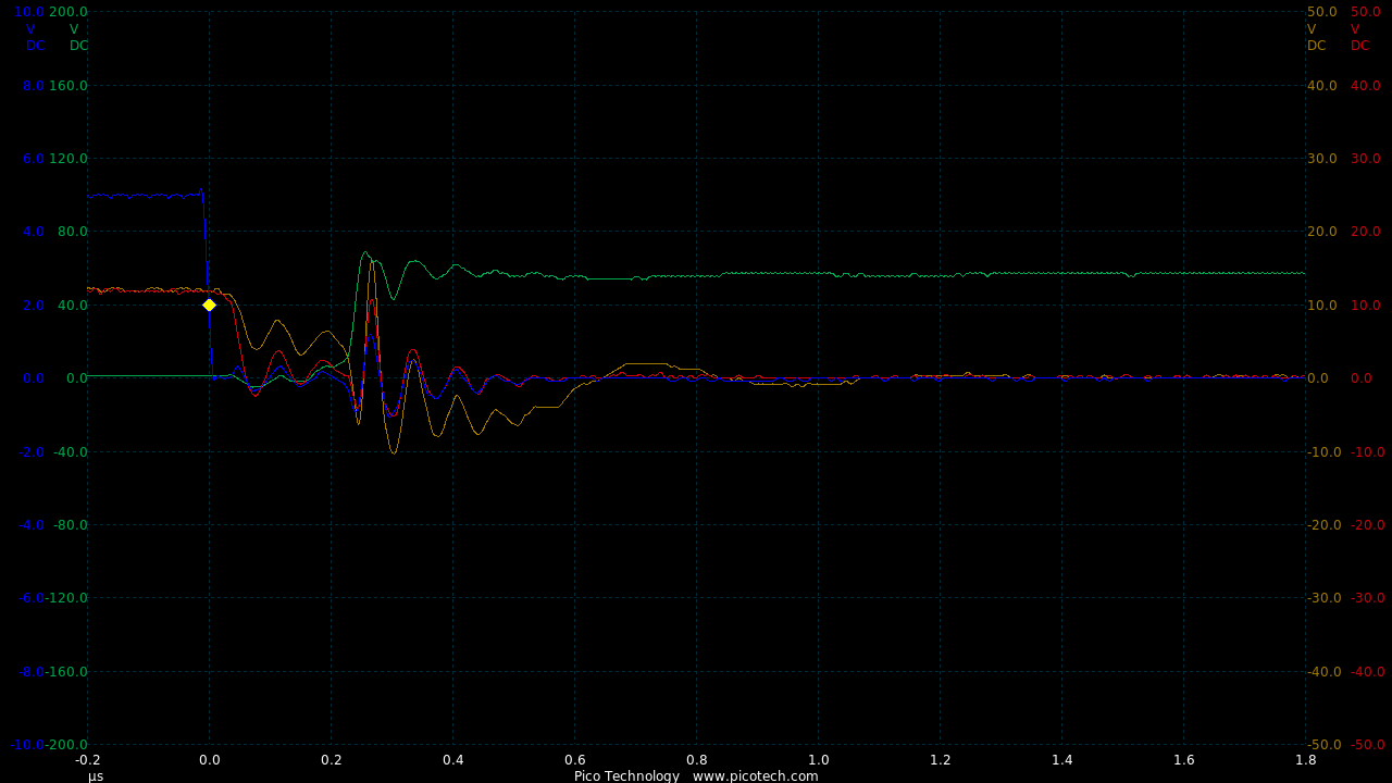
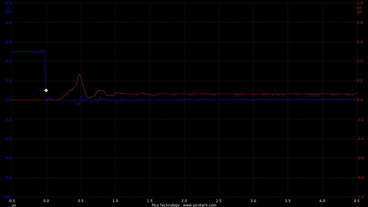
Adding a Schottky parallel diode (D3) makes quite a difference.
Also gate resistor of 11R and a gate discharge diode were added so the turn on times were extended.
TIME:200nS/div, Blue:TP1(2vDC/div), Orange:TP2(10vDC/div), Red:TP3(10vDC/div), Green:TP4(40vDC/div).
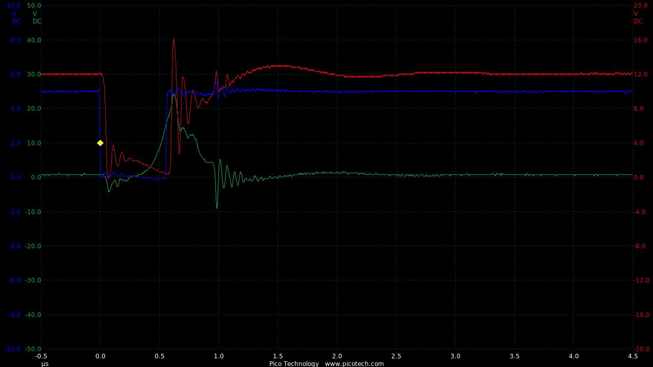
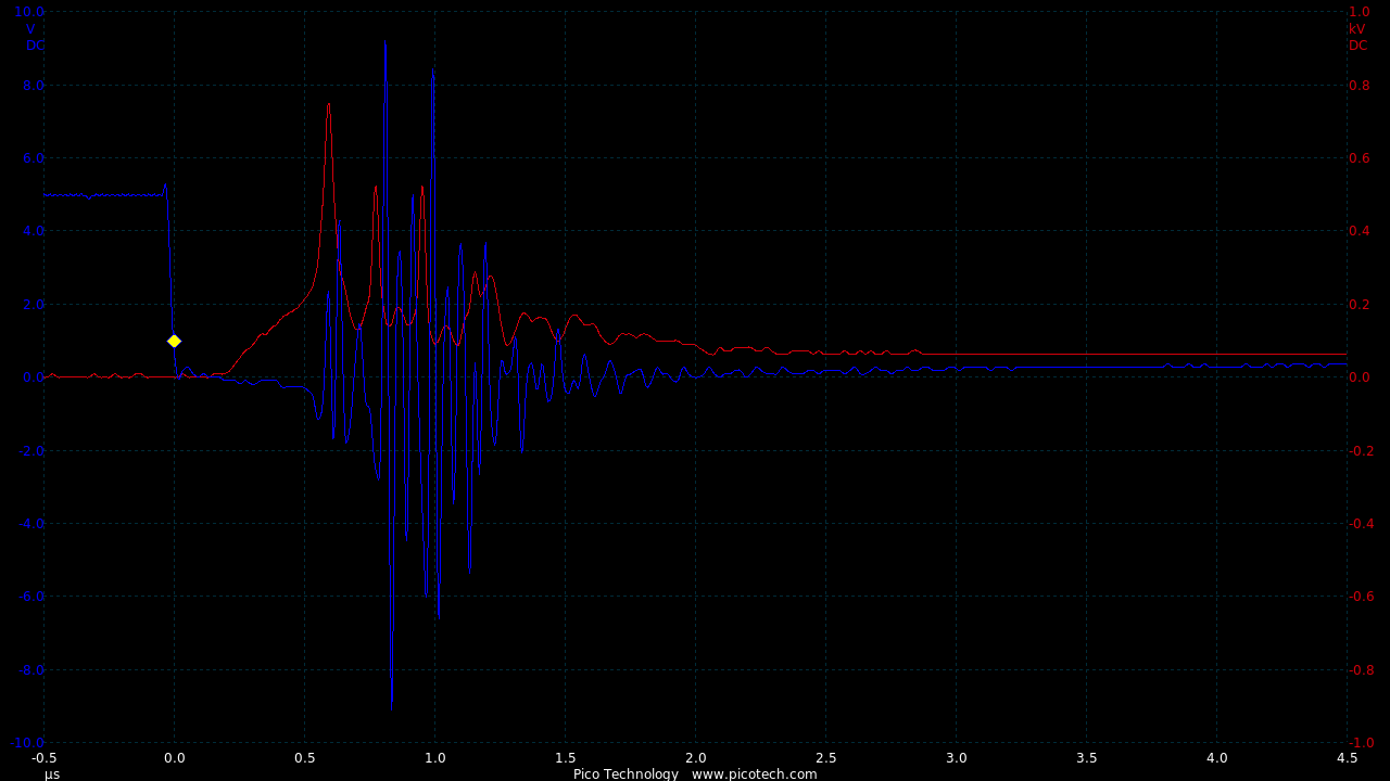
It seems D3 is just accounting for the long wires connecting the gate circuit.
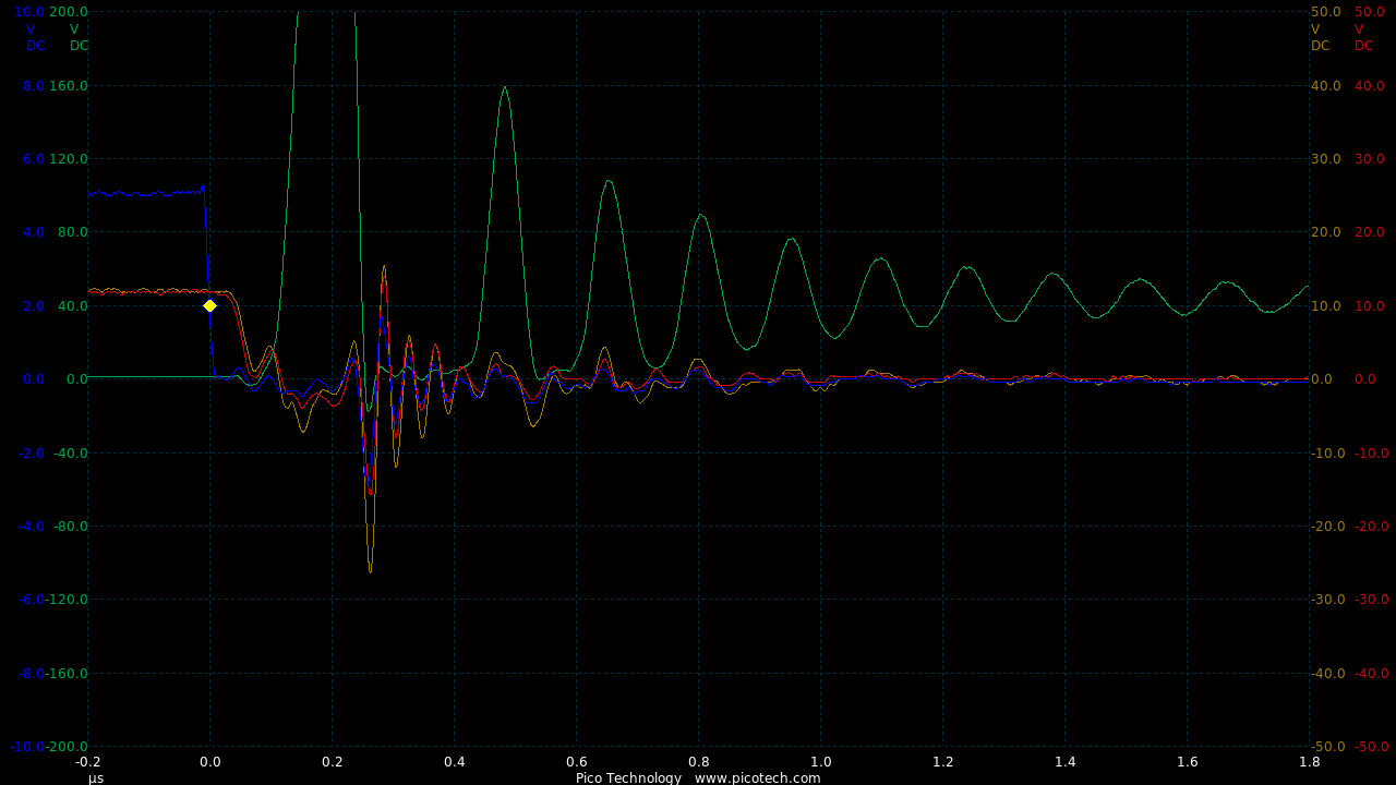
So these were shortened and the result was also better (without D3).
TIME:200nS/div, Blue:TP1(2vDC/div), Orange:TP2(10vDC/div), Red:TP3(10vDC/div), Green:TP4(40vDC/div).
And now we have success with the high power IGBT.
This is minimum mark:
TIME:500nS/div, Blue:TP1(2vDC/div), Orange:TP2(10vDC/div), Red:TP3(10vDC/div), Green:TP4(200vDC/div).
This is with more (about 5%) mark:
TIME:500nS/div, Blue:TP1(2vDC/div), Orange:TP2(10vDC/div), Red:TP3(10vDC/div), Green:TP4(200vDC/div).
It's still not perfect as the gate is being taken up to +50vDC (on a 12vDC motor) for about 10nS with higher mark, but at least the IGBT is working stably.
Testing at 30Hz PWM frequency on the milk float motor on 4 x 12v/80Ah batteries
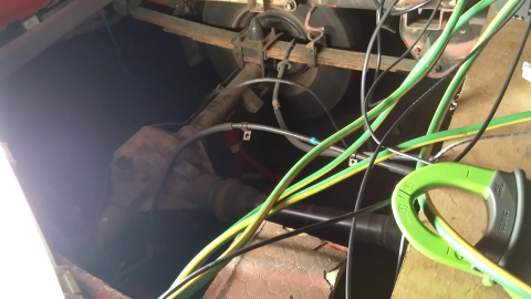
Minimum mark:
TIME:500nS/div, Blue:TP1(2vDC/div), Red:TP4(200vDC/div).
Spinning up:
TIME:500nS/div, Blue:TP1(2vDC/div), Red:TP4(200vDC/div).
This is probably cleaner as the the milk float motor is series wound and has no permanent magnets.
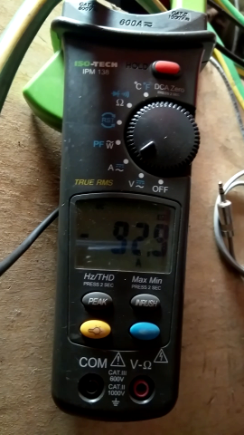
Peak current during testing 92.9 amps:
The main cause of this has to be RF feedback as it's affecting the MCU output signal.
Adding some shielding will probably stop this.
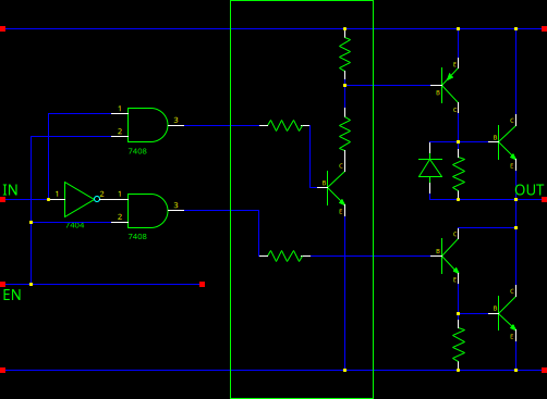
Trinary 3-Phase
Now the basic power testing shows it'll work, the testing moves to the patent 3-phase trinary controller.
UnoBLDC.cpp
static const char Trinary[][TRITS+1] = {
    "++-",
    "+ -",
    "+--",
    "+- ",
    "+-+",
    " -+",
    "--+",
    "- +",
    "-++",
    "-+ ",
    "-+-",
    " +-"
};
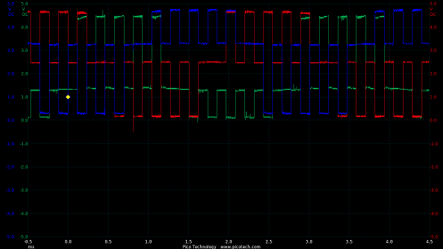
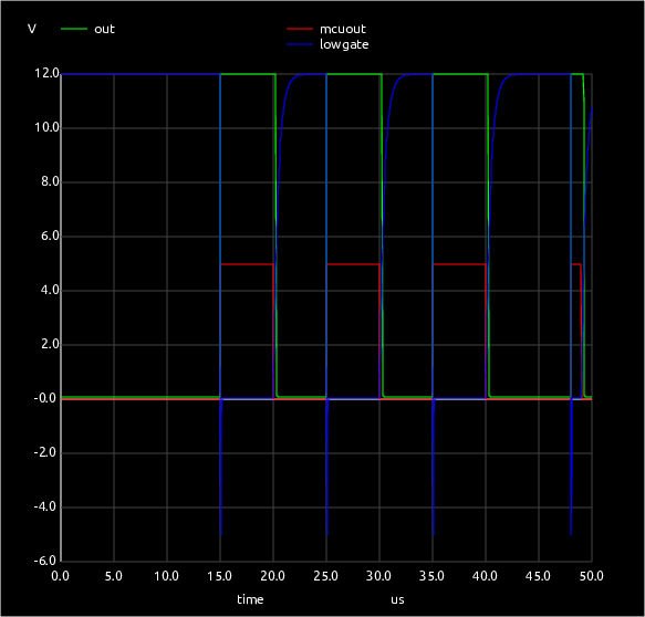
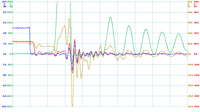
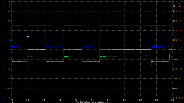
TIME:500uS/div, Blue:TP1(1vDC/div), Brown:TP2(1vDC/div), Green:TP3(1vDC/div).
The trimmers were set to arbitrarily offset the open-circuit states so we can see them.
Also the mark and space were just short and equal so we can see the switching.
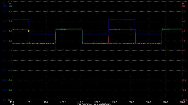
Just to see the transitions of a single channel (blue trace), from high to off then low, off and back to high
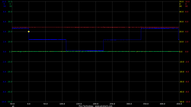
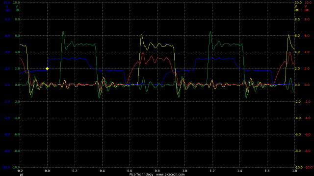
TIME:50uS/div, Blue(2vDC/div), Red(2vDC/div), Green(10vDC/div), Yellow(10vDC/div).
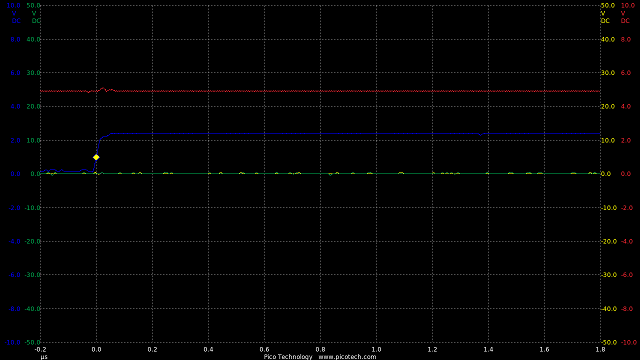
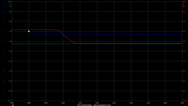
Off to low:
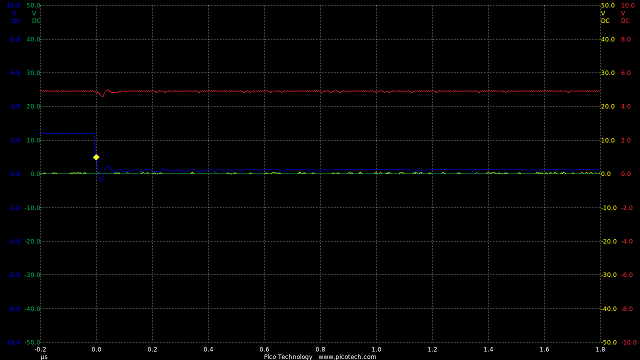
TIME:200nS/div, Blue(2vDC/div), Red(2vDC/div), Green(10vDC/div), Yellow(10vDC/div).
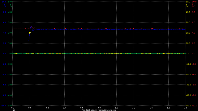
Low to off:
TIME:200nS/div, Blue(2vDC/div), Red(2vDC/div), Green(10vDC/div), Yellow(10vDC/div).
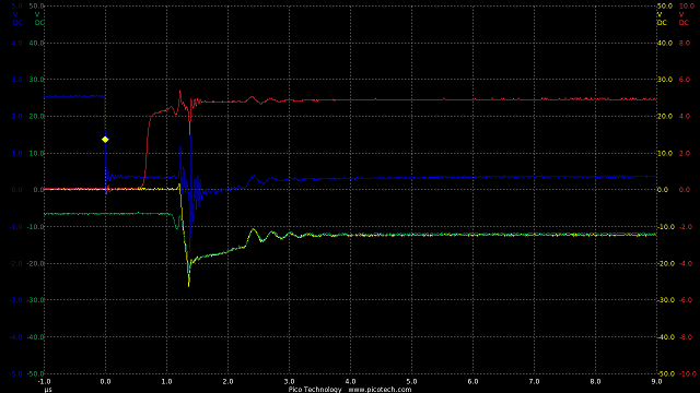
Off to high:
TIME:200nS/div, Blue(2vDC/div), Red(2vDC/div), Green(10vDC/div), Yellow(10vDC/div).
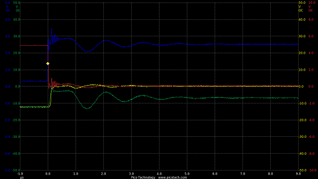
High to off:
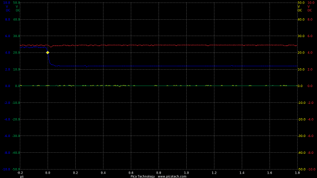
TIME:200nS/div, Blue(2vDC/div), Red(2vDC/div), Green(10vDC/div), Yellow(10vDC/div).
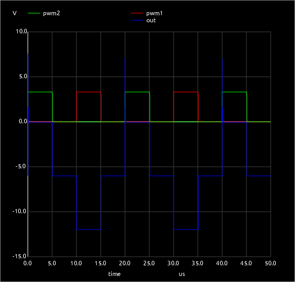
Simple PWM testing
Using a single channel:
TIME:500uS/div, Blue:TP1(2vDC/div), Brown:TP2(2vDC/div).
TIME:100nS/div, Blue:TP1(2vDC/div), Brown:TP2(2vDC/div).
TIME:100nS/div, Blue:TP1(2vDC/div), Brown:TP2(2vDC/div).
IGBT testing:
TIME:1mS/div, Blue:TP1(2vDC/div), Brown:TP2(4vDC/div).
TIME:1uS/div, Blue:TP1(2vDC/div), Brown:TP2(4vDC/div).
TIME:1uS/div, Blue:TP1(2vDC/div), Brown:TP2(4vDC/div).
Low side:
TIME:100uS/div, Blue:TP1(2vDC/div), Red:TP2(1vDC/div), Green:TP4(10vDC/div), Yellow:TP5(10vDC/div).
TIME:1uS/div, Blue:TP1(2vDC/div), Red:TP2(1vDC/div), Green:TP4(10vDC/div), Yellow:TP5(10vDC/div).
TIME:1uS/div, Blue:TP1(2vDC/div), Red:TP2(1vDC/div), Green:TP4(10vDC/div), Yellow:TP5(10vDC/div).

High side:
Optocoupled Gate Driver
NOTE: The HCPL-3120 gate driver will not work under 15vDC.
These tests were done at 18vDC which seemed to be the minimum to achieve stability.
For the test, R1 was tuned to give the shortest but cleanest transition on the IGBT gate.
This was 13R4.
TIME:200nS/div, Blue:TP1(2vDC/div), Red:TP2(4vDC/div).
TIME:200nS/div, Blue:TP1(2vDC/div), Red:TP2(4vDC/div).
TIME:20uS/div, Blue:TP1(2vDC/div), Red:TP2(4vDC/div).
Transition times are in the order of 200nS, with a delay about the same so fast for an optocoupled part.
The noise would be improved by using shorter connections.
There is also the HCPL-3020 which works down to 10v so is suitable for 12vDC single rail circuits.
Op Amp for Trinary
Due to it's 84MHz CPU speed the Arduino Due is a better choice for an SVM controller.

      MOV r4, REG_PIOC_SODR
      MOV r5, REG_PIOC_CODR
      MOV r6, REG_PIOC_OER
      MOV r7, REG_PIOC_ODR
      MOV r8, REG_PMC_PCER0

      MOV r0, #0xFF
      LSL r0, #2

      MOV r9, #0x2000
      STR r9, [r8]                ; PMC to enable Parallel I/O Controller C (PIOC, PID13)

  L1: STR r0, [r4]                ; HIGH
      STR r0, [r6]                ; output
      NOP
      NOP
      NOP
      NOP

      NOP
      STR r0, [r7]                ; OFF (input)
      NOP
      NOP
      NOP

      STR r0, [r5]                ; LOW
      STR r0, [r6]                ; output
      NOP
      NOP
      NOP

      NOP
      STR r0, [r7]                ; OFF (input)

      B L1                        ; repeat
TIME:20nS/div, Blue:TP1(1vDC/div).
Here you can see the waveform running at about 14MHz.
Using the MicroChip MCP6002 which is rated at 1MHz, and at a lower frequency of about 3kHz it can be see that the theory is good,
but it's just far too slow to be useful.
TIME:100uS/div, Blue:TP1(1vDC/div), Red:TP2(2vDC/div), Green:TP3(2vDC/div).
TIME:5uS/div, Blue:TP1(1vDC/div), Red:TP2(2vDC/div), Green:TP3(2vDC/div).
Transition times are in the region of 5uS.
A 15MHz TI RC4560 was also tested which has better transition times in the region of 1uS.
TIME:500nS/div, Blue:TP1(1vDC/div), Red:TP2(2vDC/div), Green:TP3(2vDC/div).
...but the part seemed to have a problem running from a single rail supply
TIME:5uS/div, Blue:TP1(1vDC/div), Red:TP2(2vDC/div), Green:TP3(2vDC/div).
Low side seems to switch OK, but the high side was also switching for low side.
Reverting to Bipolar Design
Checking the bipolar transition times at approx 1MHz.
TIME:200nS/div, Blue:TP1(1vDC/div), Red:TP2(1vDC/div), Green:TP3(1vDC/div).
So here transition times are in the region of 100nS.
Adding the SN74LS14 Schmitt Trigger Inverters brings transition times to 50nS with around 100nS delay.
TIME:200nS/div, Blue:TP1(2vDC/div), Red:TP3(2vDC/div), Green:TP4(2vDC/div), Yellow:TP5(2vDC/div).
All these times are an order of magnitude shorter than the 1uS needed, so this will work well.
The output is a bit noisy due to the wiring, but the Schmitt Trigger inverters seem fine with 3v3 logic input.
At 3kHz the 3v3AC trinary to twin 5vDC binary is clear.
TIME:100uS/div, Blue:TP1(1vAC/div), Green:TP4(2vDC/div), Yellow:TP5(2vDC/div).
Electromagnets
Since a new patent motor is being designed this needs some research into inductors and magnetic circuitry.
Some preliminary research shows that the most powerful magnets for the same volume are electromagnets.
Also the copper in an electromagnet is much cheaper and easier to use than cobalt or neodymium, and far more environmentally friendly.
It is possible, and the subject of more research, that a motor using an electromagnetic exciter
would be less efficient than one made from permanent magnets.
	Volts	Current	Ohms
air	0.822	3	0.274		-0.002
	1.14	4.2	0.271		0.001
	1.52	5.6	0.271	0.272	0.001
bar	0.833	3.2	0.260		0.007
	1.17	4.3	0.272		-0.005
	1.54	5.7	0.270	0.268	-0.003

air	5.1	4.8	1.063		0.016
	4.3	3.9	1.103		-0.024
	3.45	3.2	1.078		0.001
	2.55	2.4	1.063		0.016
	1.85	1.7	1.088	1.079	-0.009
bar	1.85	1.7	1.088		0.044
	2.6	2.3	1.130		0.002
	3.49	3.1	1.126		0.006
	4.37	3.8	1.150		-0.018
	5.25	4.5	1.167	1.132	-0.034
CoilTest.ino
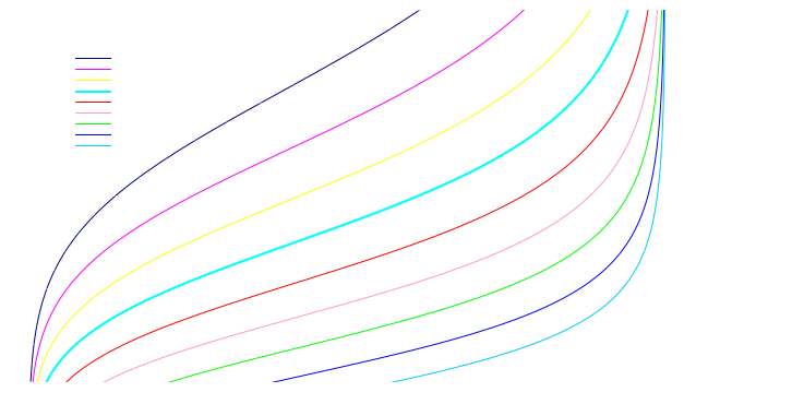
Field Strength of a Planar Solenoid
Total volume is 55mm x 1.12mm = 61.6mm2 (not subtracting the central hole)
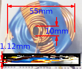
So the only way to work this out is by treating each loop separately.
From Magnetic Field of Current Loop (HyperPhysics / Georgia State University)
B = μ0 x current / ( 2 x radius )
current = 6A
| 5.00 mm |
75.398 |
0.754 |
31.42 mm |
| 5.53 mm |
68.205 |
0.682 |
34.73 mm |
| 6.11 mm |
61.697 |
0.617 |
38.39 mm |
| 6.75 mm |
55.811 |
0.558 |
42.44 mm |
| 7.47 mm |
50.486 |
0.505 |
46.92 mm |
| 8.25 mm |
45.669 |
0.457 |
51.87 mm |
| 9.13 mm |
41.312 |
0.413 |
57.34 mm |
| 10.09 mm |
37.370 |
0.374 |
63.38 mm |
| 11.15 mm |
33.805 |
0.338 |
70.07 mm |
| 12.33 mm |
30.580 |
0.306 |
77.46 mm |
| 13.63 mm |
27.662 |
0.277 |
85.63 mm |
| 15.07 mm |
25.023 |
0.250 |
94.66 mm |
| 16.65 mm |
22.636 |
0.226 |
104.65 mm |
| 18.41 mm |
20.476 |
0.205 |
115.68 mm |
| 20.35 mm |
18.522 |
0.185 |
127.88 mm |
| 22.50 mm |
16.755 |
0.168 |
141.37 mm |
| 631.408 |
6.314 |
1.184 m |
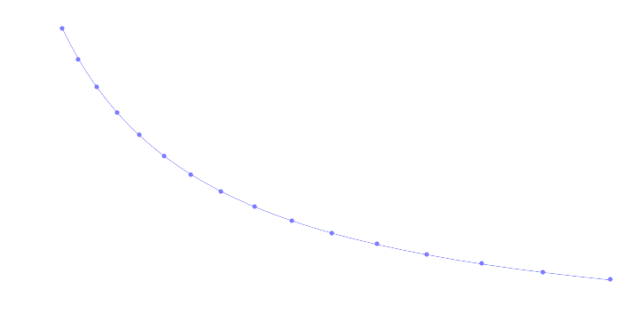
Total field strength is 0.1mT per Amp or 1 Gauss/A.
So this is the field strength at the centre of the magnet, but in a motor the rotor would be close to all the windings, including the outer loops.
This means the effect on a large flat plate would be more that something requiring the field being focused at the centre.
Also given that the idea is to create a field vector, rather than some localised field at the magnet, the graph above is not portraying the true strength.
Electric Measurements
Measuring voltage and current accurately is a problem.

L298
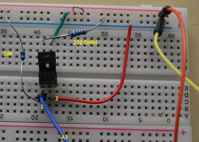
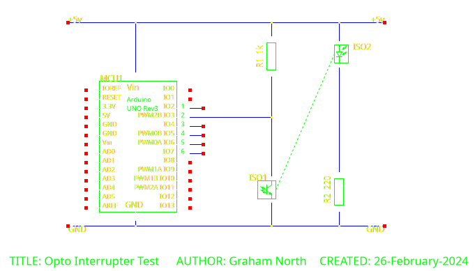
ITR9608
Photo Interrupter Sensor Questions