Varying VR1 varies the time period killing two bird with one stone.
The software can use this instead of an internal timer making it separate to the software and this provides analogue control without ADC input.
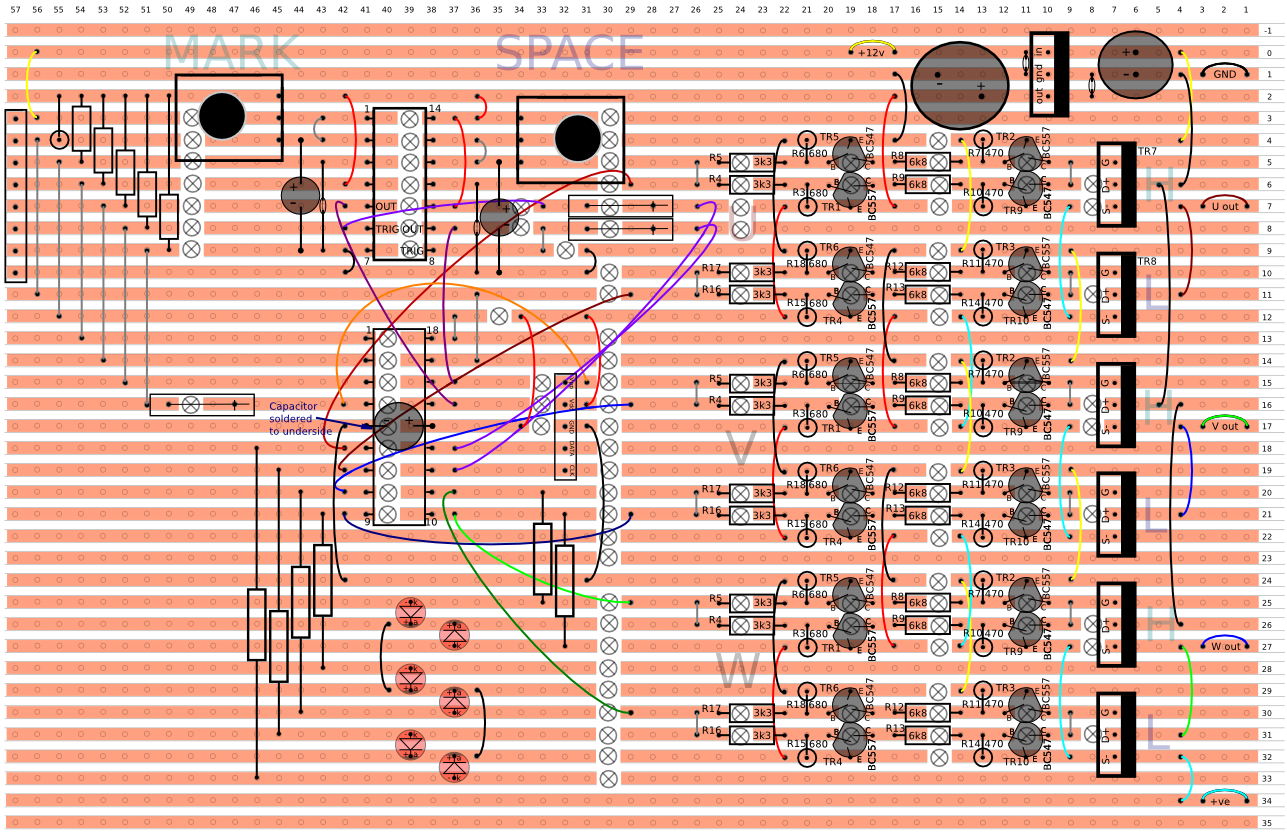
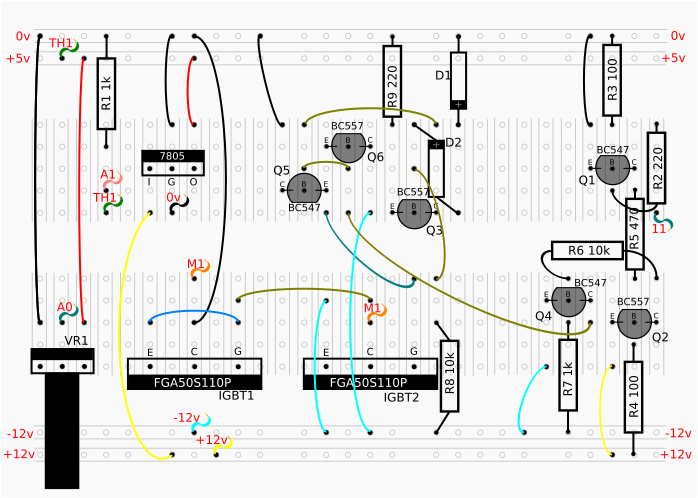
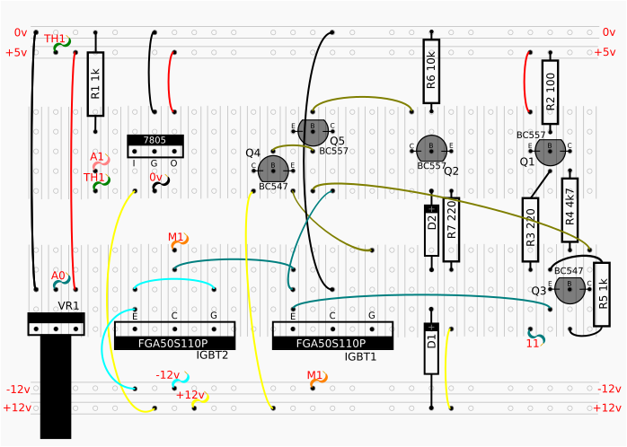
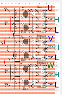
This circuit discharges the gate with a transistor and charges using a resistor for both high and low sides.
This means fast off times, but slower on times removing crossover shoot-through.
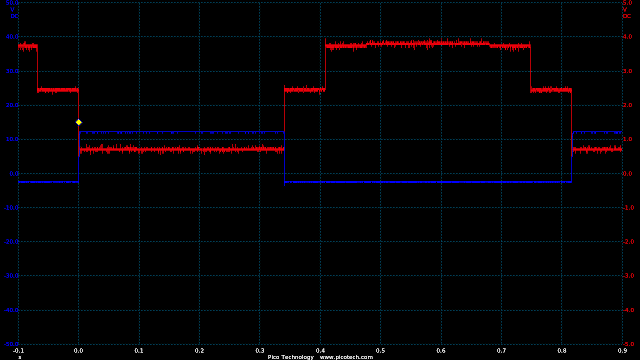
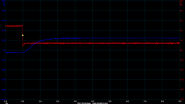
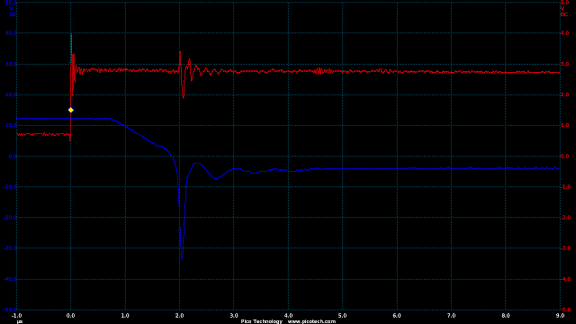
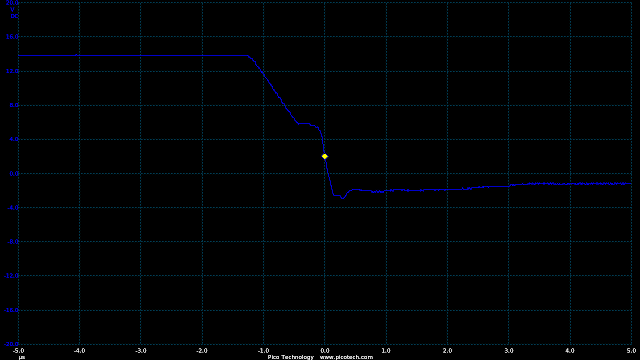
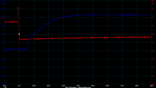
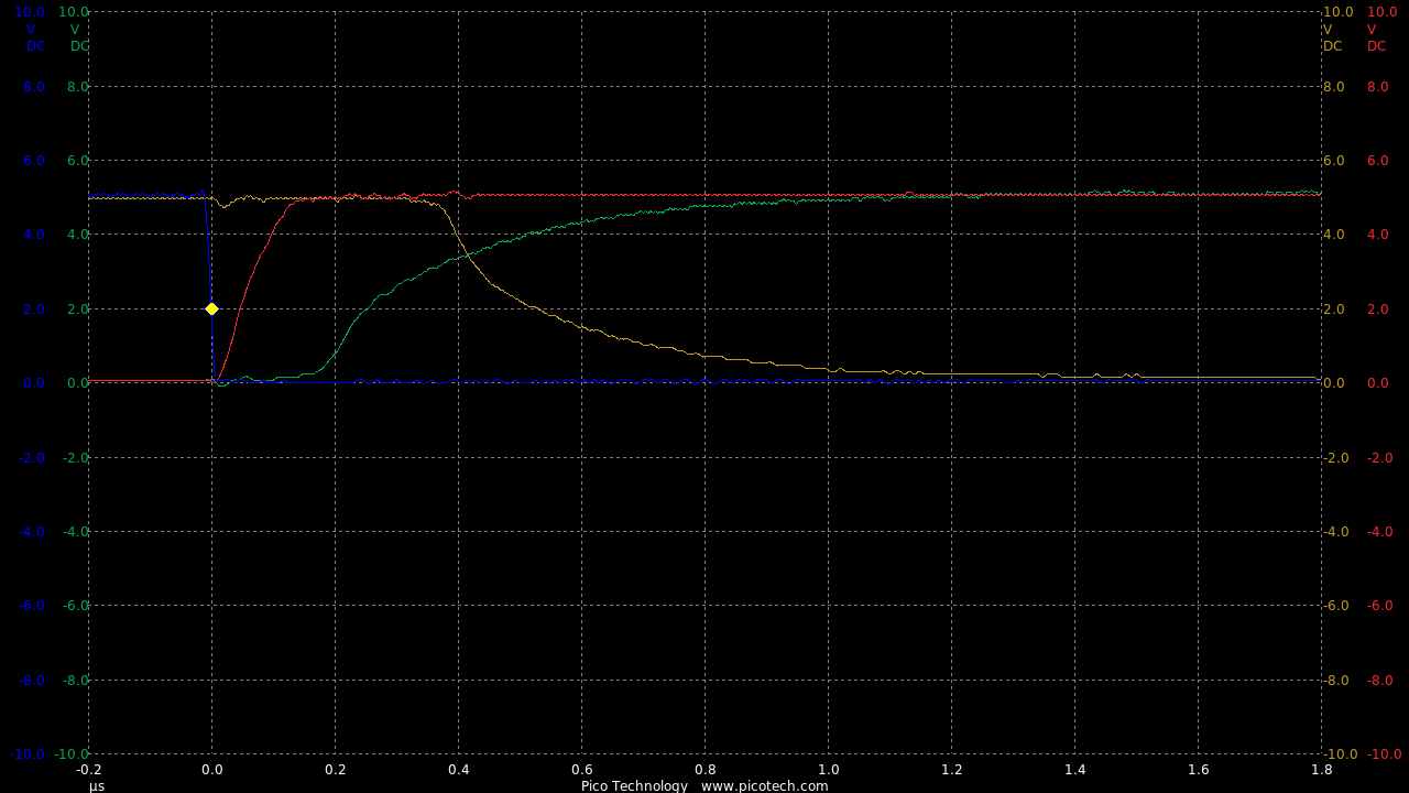
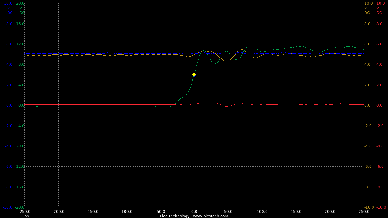
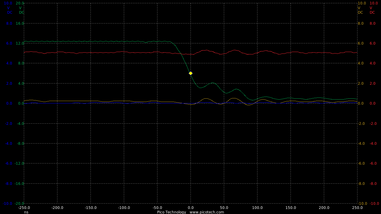
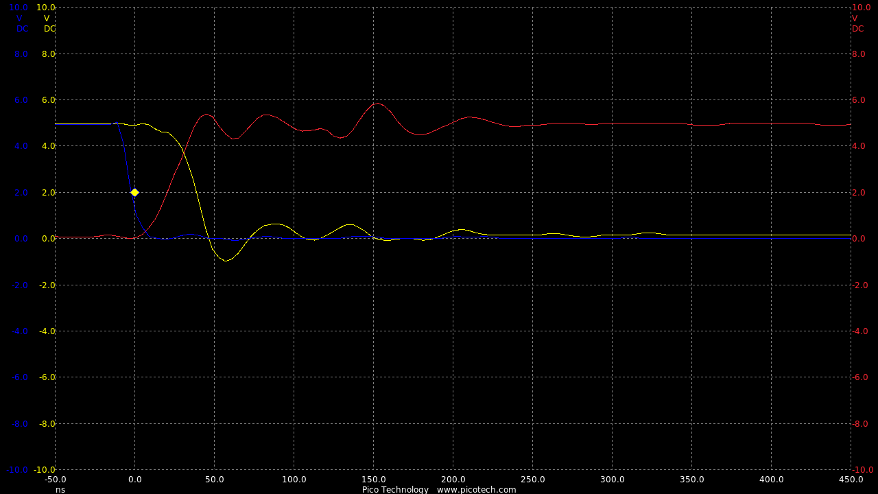
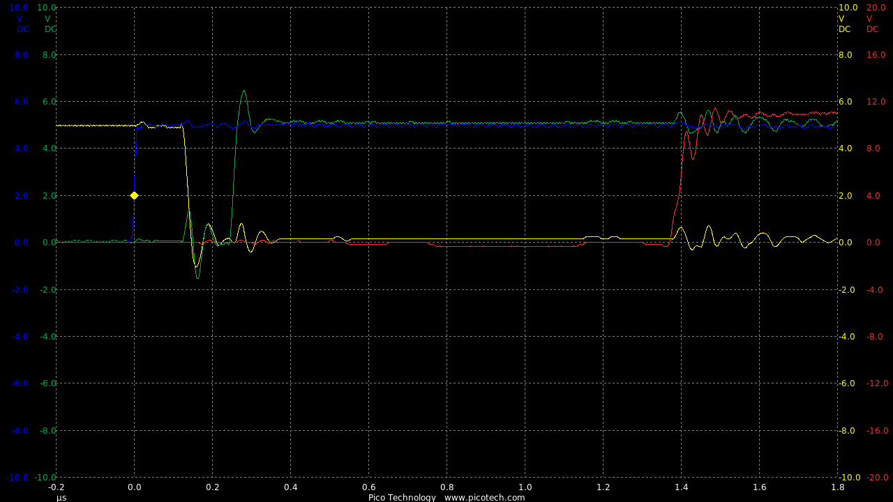
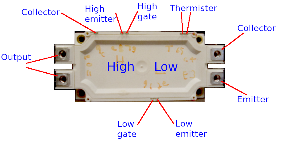
Traces taken from IGBT2 gate, vs MCU1 IO9
0.1sec/div:
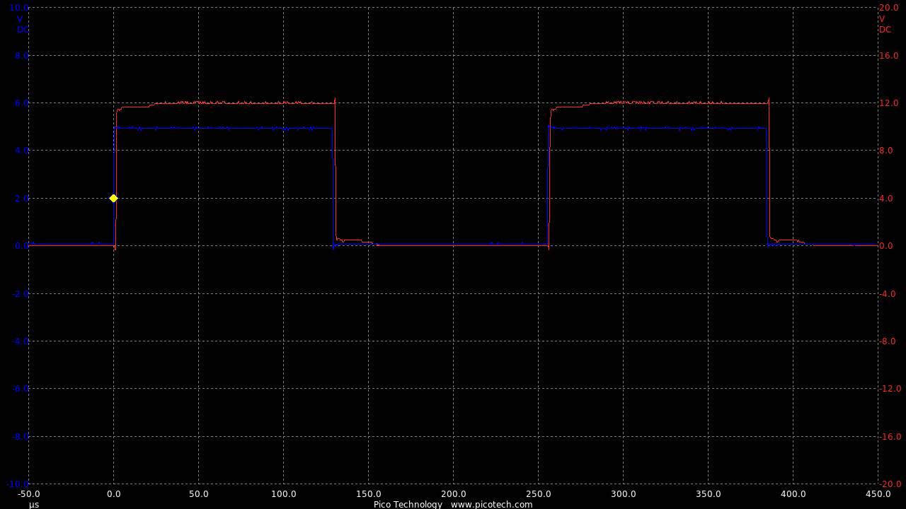
1msec/div:
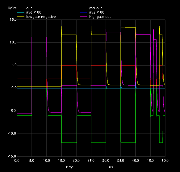
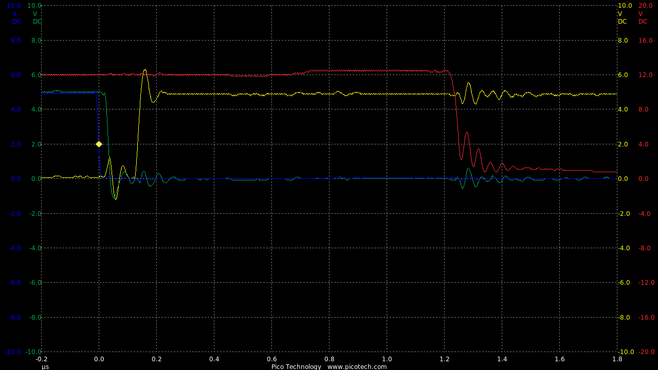
1usec/div:
1msec/div:
1usec/div:
So the fall times (switch off) is fast (1uS), but the rise times (switch on) are very slow at 1,000uS
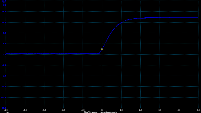
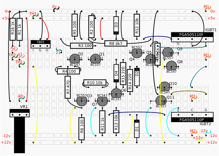
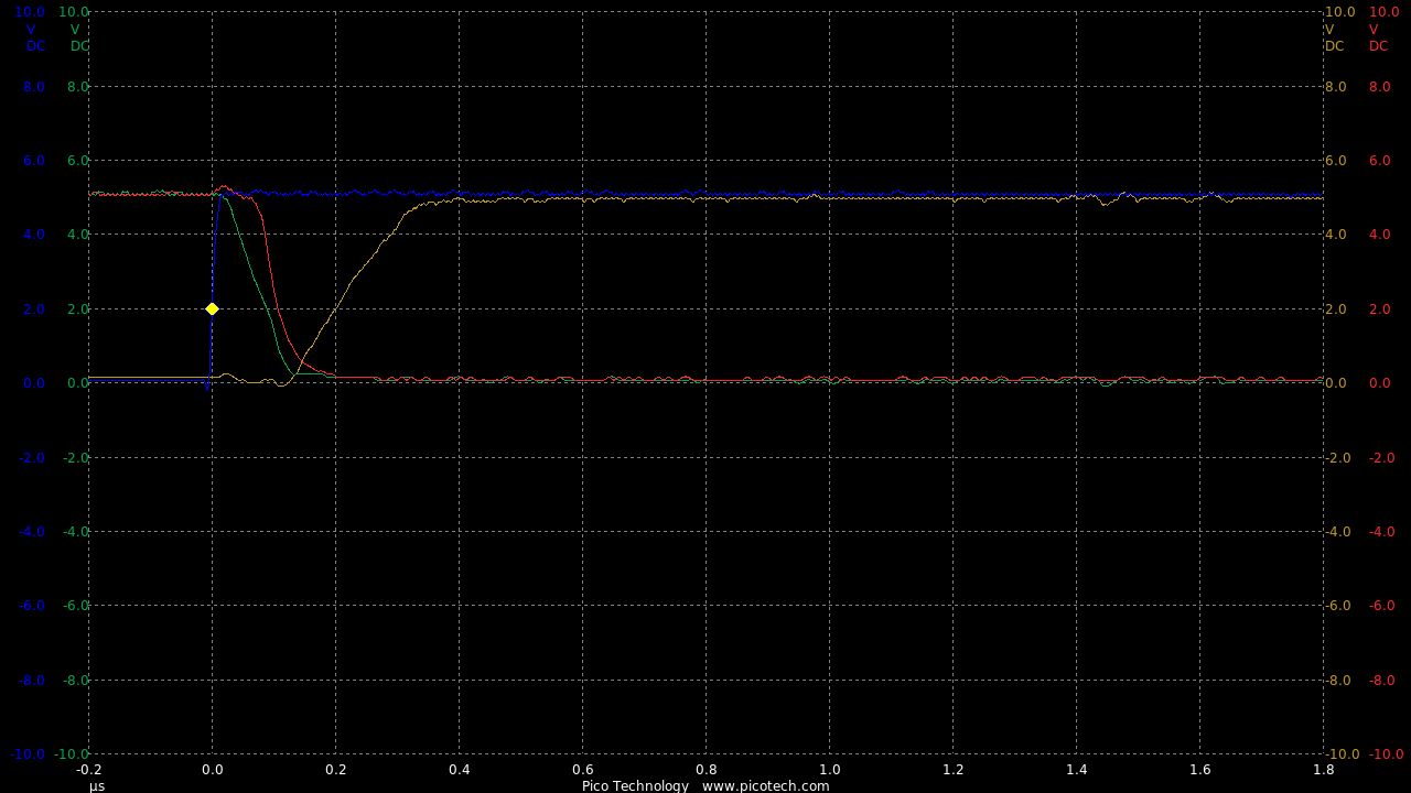
Improving Switch-On Speed
Part of the problem in this circuit was the slow time of the opto release.
This is improved with a base switch-off resistor (R3/R5) and by switching the base from the supply instead of the collector.
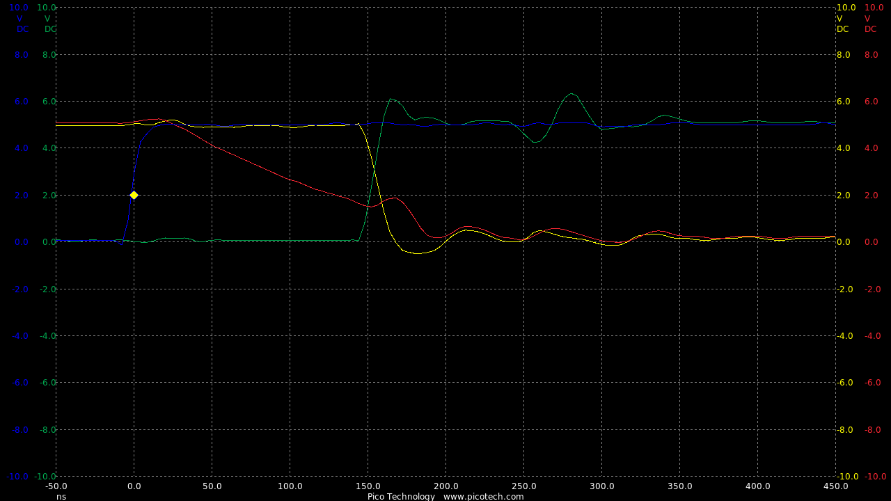
Now we are seeing speeds much closer to the theoretical RC circuit of the 1k charge resistor and gate capacitance.
The 11.5uS is for the time constant of the RC circuit (to ~63%).
10usec/div:
Class D Trinary Amplifier
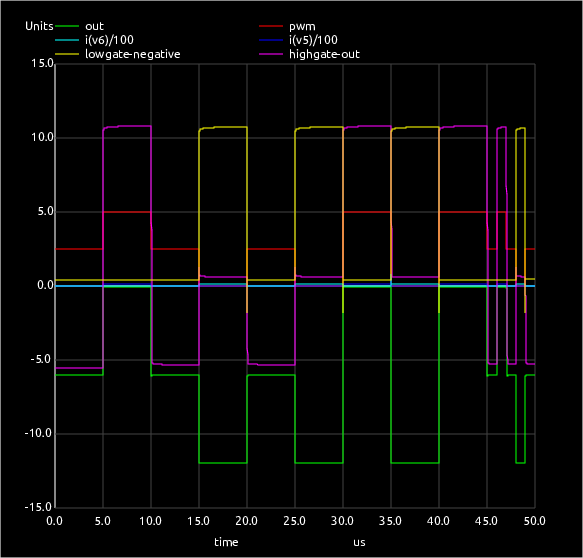
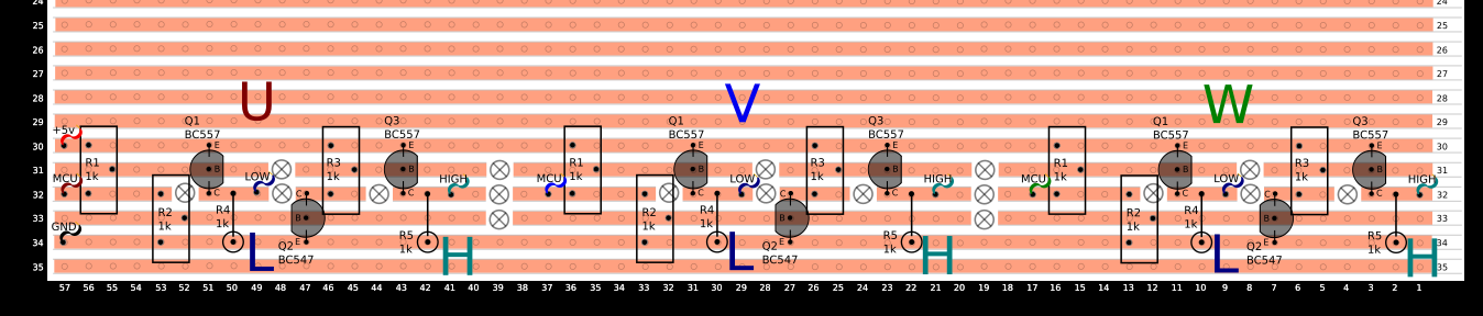
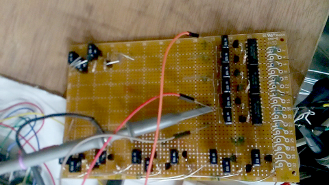
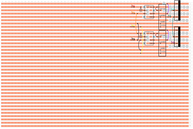
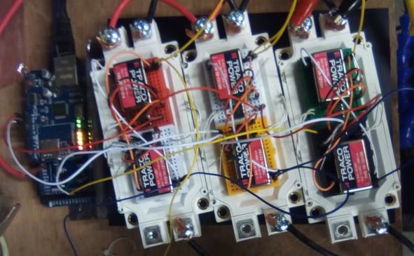
Here we are (finally) starting the development of the full class D trinary amplifier.
The parts of the test extend from the PWM testing done in the Component Testing.
So this is now showing the single output from the Arduino is amplified to the motor and can control the switching of both IGBTs independently.
This is true 3-state trinary amplification of the PWM inputs just as a classic binary PWM output of a class-D audio amplifier.
More importantly this can never suffer from shoot-through as it has does not have the fourth state of both IGBTs on by design.
Thus eradicating the need for complex shoot-through detection and elimination electronics.
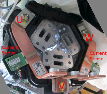
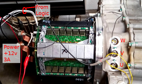
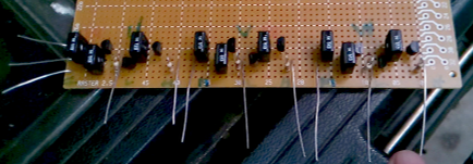
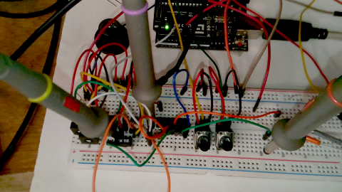
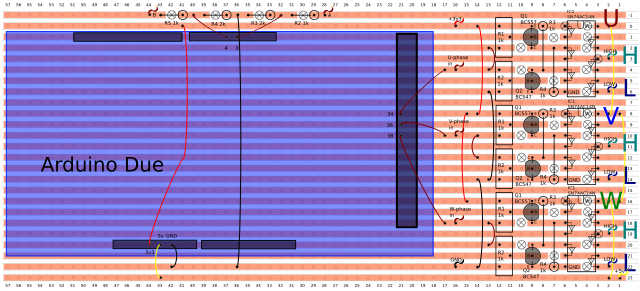
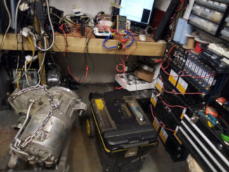
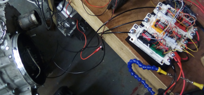
Hooking Up To Motor
This was tested on the Tesla model S rear drive unit.
Also see here for the MCU software
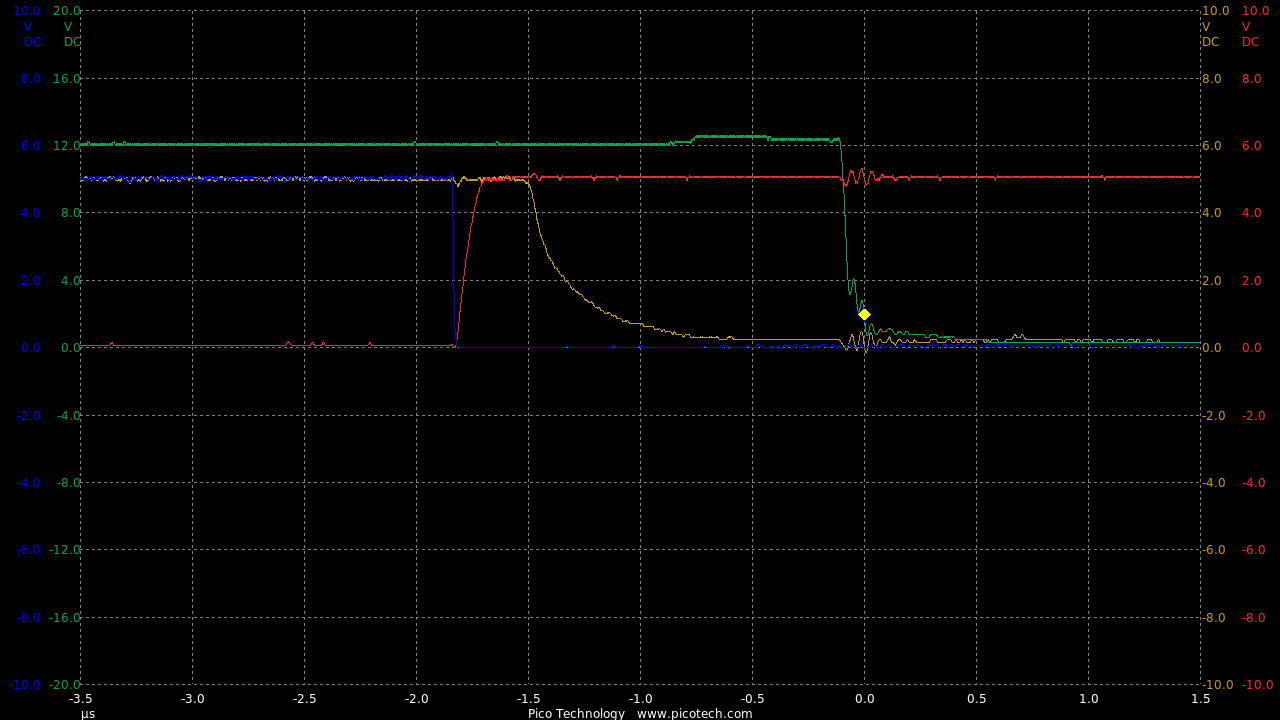
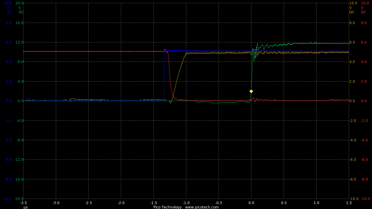
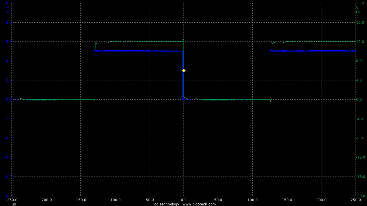
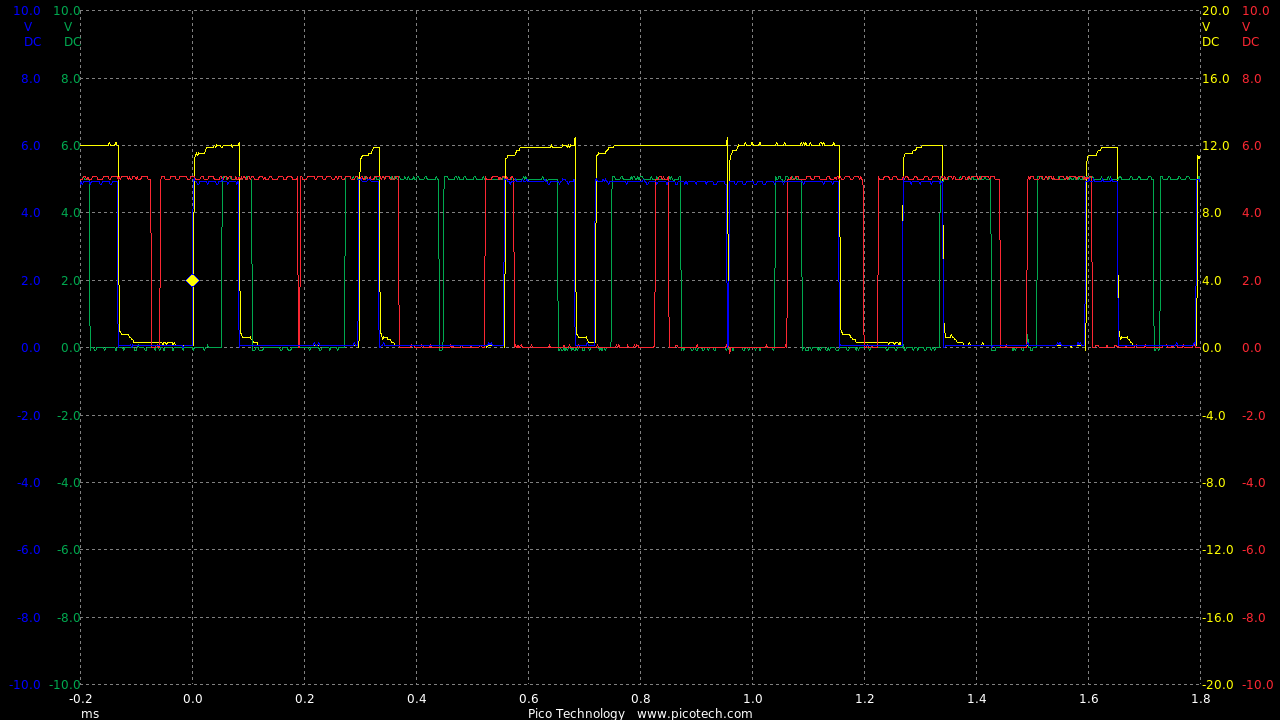
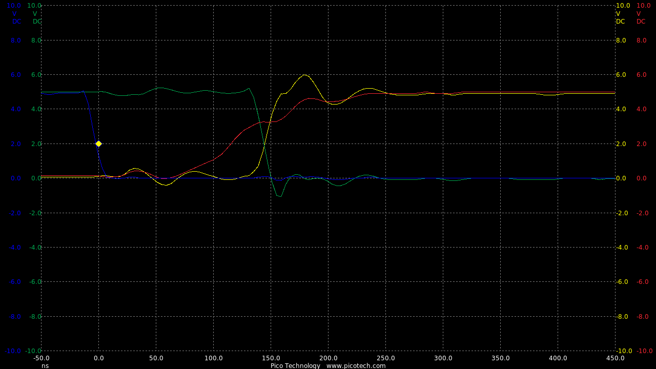
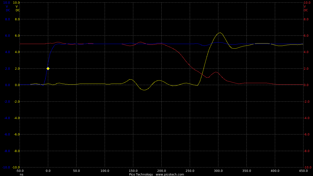
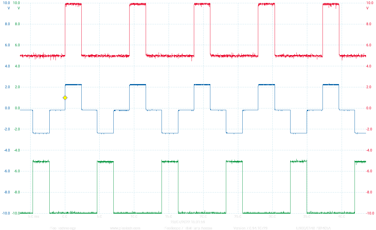
Checking V-phase Motor input (PWM ~4kHz, field rotation ~1kHz)
TIME:200uS/div, Blue:MCU V-phase(2vDC/div), Red:MCU W-Phase(2vDC/div), Green:MCU U-Phase(2vDC/div), Yellow: Motor V-phase(4vDC/div).
Adding Schmitt Triggers
7414 Schmitt Trigger inverters are very fast, in the order of 10nS switch times.
This is much faster than the BC5x7B circuits so it makes sense to use one as an inverter.
Also having 2 in series provides a good buffered output.
To control the steering box a motor was attached and this is going to be controlled by servo.
Power is controlled using a H-bridge circuit which is fed with PWM to give propotional control in both directions.
Since the feedback part is not created the motor (MV) is controlled by simply differentiating the control (SP) movement.
This gives something similar to servo control, but without any accuracy.