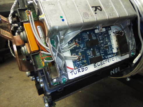
This page is about the Turbo-Electric High Energy conversion of the Tesla Model-S Rear Drive Unit which can be bought as salvage on eBay and other places.
It's based around the use of the unit in the Mass-EV electric car project.
The unit was originally bought as a kit from EV-West which included a controller produced by EV-Controls and parts were incrementally upgraded
More details about the original EV-West/EV-Controls kit here
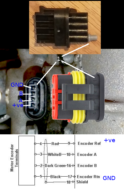
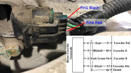
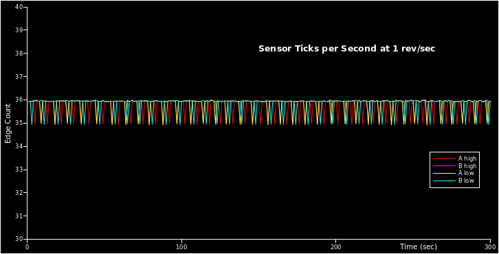
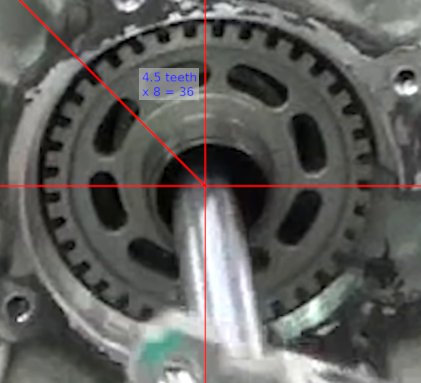
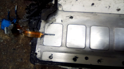
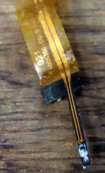
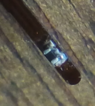
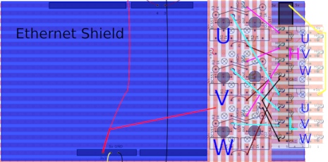
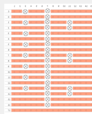
Found by experimentation that the sensor wheel has 36 teeth:
This is slightly below the stator frequency due to induction motor slip.
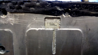
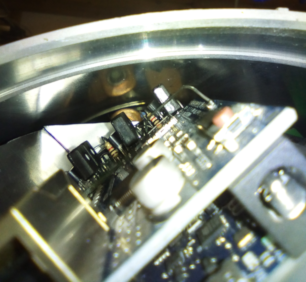
Confirmed in a teardown:
Max speed of the motor (according to Tesla) is 18,000 rpm or 300 revs/sec.
Max frequency from sensor is 300 x 36 = 10.8 kHz.
High Power Upgrade
The original motor was designed for a 300vDC battery and was down-tuned to limit the power to approx 250kW which is about 800A.
In the Mass-EV project the battery is 33 x 12vDC AGM batteries, which have a rest voltage of 12.6vDC and max 13.8vDC.
This means a pack voltage of between 415v and 455v.
Also the car has 3 packs in parallel each capable of 600A, giving 1,800A
Also the IKW75N60T IGBT array is 16 x 75A (100C rating) for all 6 banks (2 directions by 3 phases).
This is a limit of 1,200A.
Since we are using our own logic board we can unleash the full power of this which is 1.2kA x 455v = 546kW or 732hp.
This is not a sustainable power as things will probably get quite hot very quickly.
With a high power cooling system it will be enough for 10secs of power to get a good standing 1/4 mile.
Also checking Wikipedia figures for torque it looks like it would be in the region of 900 lbft (1,220 Nm).
It's also possible using extreme cooling and series-parallel lithium pack to get even more power.
The IGBTs are capable of 225A and 600vDC each if held at less than 25C.
This would be 16 x 225A = 3,600A, 3600 x 600 = 2,160,000W or 2.16 MW (2897hp),
though I doubt that motor would withstand that for more than a second.
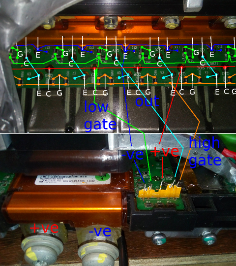
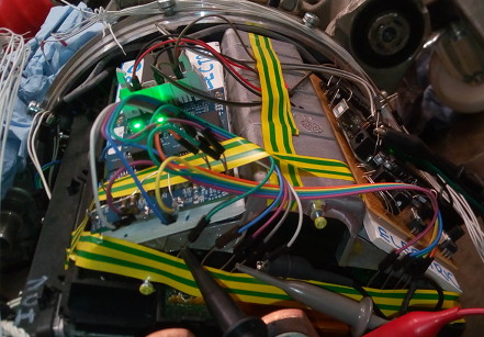
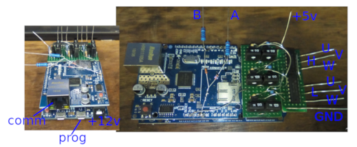
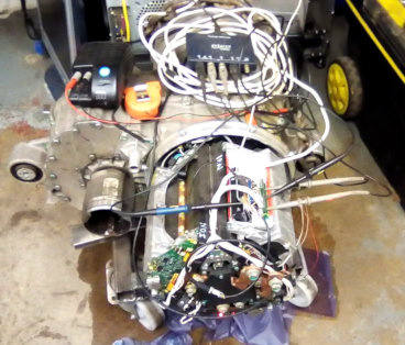
Delving in:
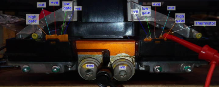
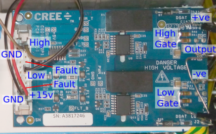
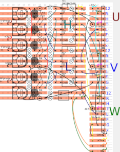
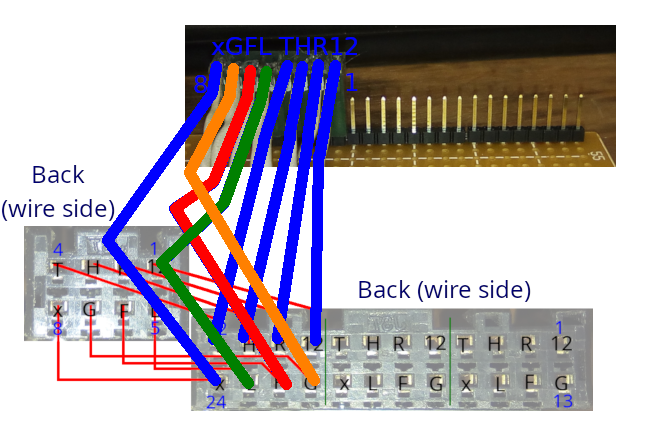
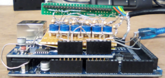
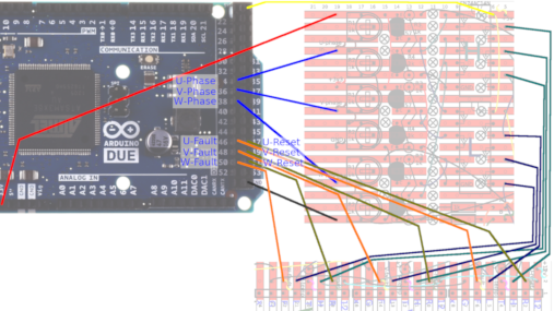
Driver board
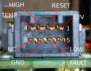
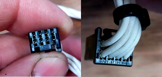
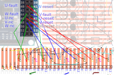
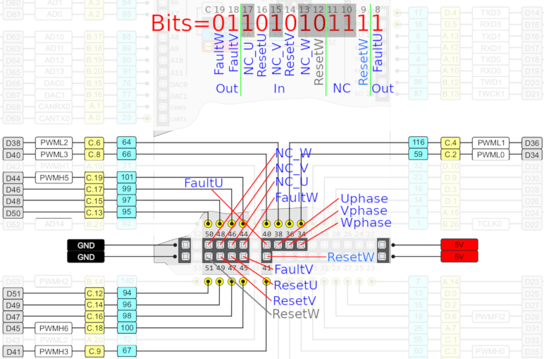
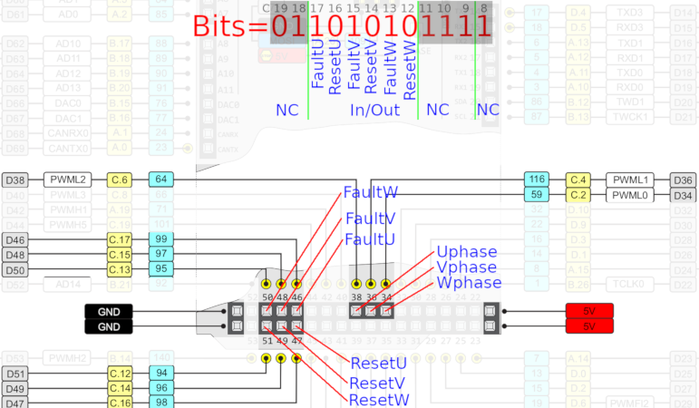
Driver board connector
The socket has a single fault output and and reset for each IGBT gate.
The RESET Line is also the GATE INHIBIT line.
Toggle the RESET low to reset if the fault line goes low then keep it tied high or it'll interrupt the gate operation.
During testing one of the original driver boards had a fault.
Replacing with another original part was just not an option, they are not available.
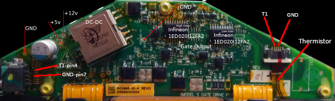
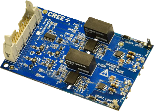
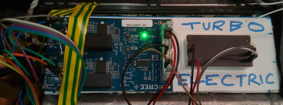
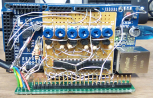
This is using a Cree/Wolfspeed CGD15HB62P1 gate driver board as a replacement for the Tesla one.
The CGD15HB62P1 is sold by both RS and Farnell, and probably others, so it's something which is readily available.
It uses the same Infineon 1ED020I12 driver so is compatible with anything which connects to the original Tesla board.
The board plus DC-DC converter comes in under £250 (inc UK VAT).
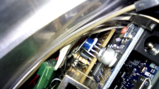
They are not the right shape to fit in the original space, but there is space above the IGBTs to fit a board so will fit inside the inverter housing.
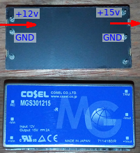
This board is intended to be used with a Cree IGBT module, so it needs some modification.
The supply is 15vDC instead of 12vDC so needs a DC-DC converter,
also the board is intended to be connected directly to the gates so a connection needs to be added before the on-board gate resistors.
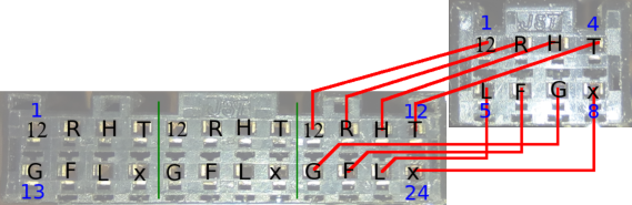
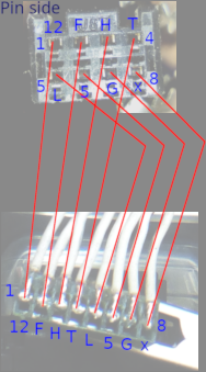
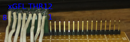
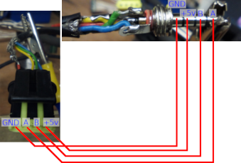
If you are intending to connect the original logic board you will also
need a lead to convert from the JST plug to the Molex socket on the CGD15HB62P1 board,
This would need to include the DC-DC converter inline.
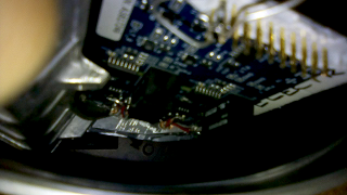
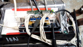
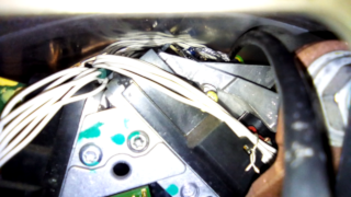
Properly mounted
..with screened leads for the gates
Plenty of space inside sleeve
Trinary Engine Controller
What is trinary control, and why is it better?
Baically it's designed in shoot-through protection, but details are here
Problems with the space probably contributed to the destruction of the inverter, so version 4 is outside the inverter housing.
This means space is no longer an issue.
Short test at roadworthy power:
Here the motor was just spun up rapidly to spike the power draw.
The motor peaked at about 40kw or about 53hp, which is approx the power of a 1.1 ltr piston engine at full power.
Enough to accelerate the car if the wheels were on the ground.
This would also be the sort of power the car would need to maintain motorway speed.
Version 4.1
Just a minor upgrade for the gate driver connections:
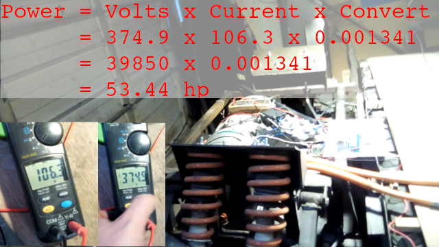
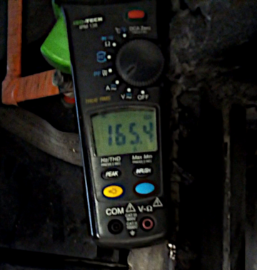
Power testing
Further testing is now being done against the brakes to see how the engine reacts under load.
Here we can see the engine running at over 150A at approx 350v, which is 52.5kw or about 70hp.
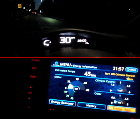
To compare this is a Nissan Leaf climbing an approx 9% incline at 30mph.
The Nissan is approx 1.5tons vs approx 4 tons for the prototype.
It's drawing about 20kw so the brake test shows this prototype is capable of doing this.
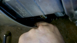
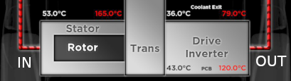
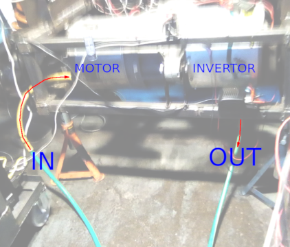
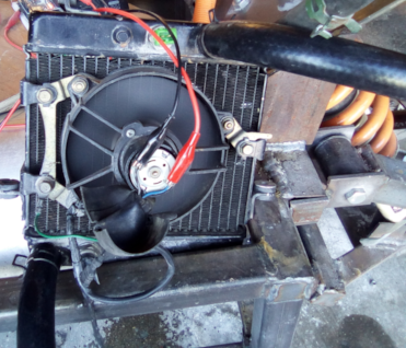
Cooling system
From shots of the cooling diagnostics, the coolant enters on the motor side and leaves on the inverter side
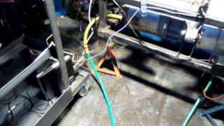
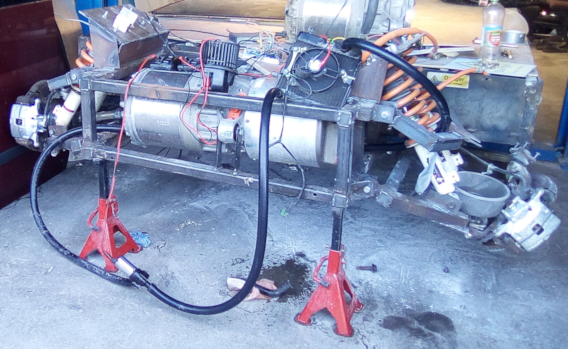
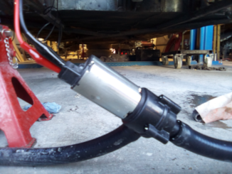
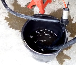
Just for testing a primitive full sacrificial system is rigged.
Upgraded
Upgraded to radiator cooled system
Added a check for flow rate